
Silos are essential structures in many industries, providing efficient storage for materials such as grain, cement, minerals, aggregates, chemicals and other bulk products. Although their primary function is storage, their structural behaviour can be complex due to the interaction between geometry, stored material, wall pressures, self-weight and environmental loads.
For structural engineers, developing a reliable analytical model is an important part of the design process. PROKON SUMO provides an environment for modelling and analysing circular and rectangular silos, enabling engineers to represent the structural system, apply appropriate loads and evaluate the resulting behaviour.
This article outlines the modelling workflow for both silo configurations, from importing geometry and defining structural elements to applying loads, running the analysis and interpreting the results
Understanding Silo Structures
Before creating a model, it is important to understand how silo geometry influences structural behaviour.
Circular silos primarily rely on their curved walls to resist pressure from stored material. Their cylindrical geometry allows circumferential forces, commonly referred to as hoop forces, to develop around the walls.
Rectangular silos, by contrast, have flat wall panels that generally rely more heavily on bending and shear resistance. The corners and connections between walls, the base and the roof can significantly influence the distribution of forces.
Depending on the configuration, a silo may consist of:
- Vertical walls
- Roof or top slab
- Base slab
- Hopper or conical discharge section
- Supporting columns or beams
- Foundation or supporting structure
Each component contributes to the overall load-transfer mechanism and should be appropriately represented in the structural model.
Modelling a Circular Silo in SUMO
Circular silos are commonly formed using a cylindrical wall surrounding the stored material. Depending on the configuration, the structure may also include a roof, base slab and hopper.
Model Setup
The first step is to establish the basic modelling parameters.

The example model uses the following parameters:
- Silo diameter = 2.14m
- Silo height = 9m
- Conical discharge section = 2.09m
- Wall thickness = 75mm
- Supporting column = 3.5m
- Beams= 1.513m
- Bracing
The model also includes bracing. The global coordinate system and structural layout should be established before creating the structural elements.
These dimensions describe the example configuration and should be checked against the intended design drawings.
Importing DWG into Prokon SUMO
- Where geometry has been prepared in AutoCAD, it can be imported into SUMO using File → Import → DWG.
- During the import process:
- Configure the import options to match the drawing geometry and units.
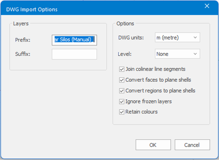
- Review the imported groups, which can help organise and isolate different structural components.
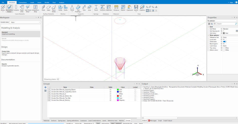
- Importing the drawing provides a starting point for constructing the analytical model, but the geometry and connectivity should still be verified.
Defining Materials and Sections
- Populate the materials and sections tables before assigning properties to the structural members.
- For the supporting steelwork, the example uses structural steel such as S355 or an equivalent grade.
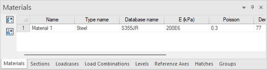
- The specified steel sections are:
- Column = 100x100x8 A1
- Supporting Beams= 80x80x8 A1
- Bracing = 50x50x8 A1
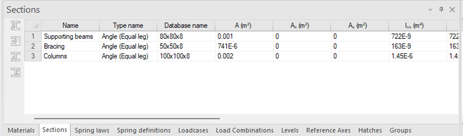
- Confirm that the section designations correspond to the intended profiles in the SUMO section library.
Building the Structural Model
Supporting frame
- Convert the imported curves into beams and columns, using groups to isolate the relevant structural lines.
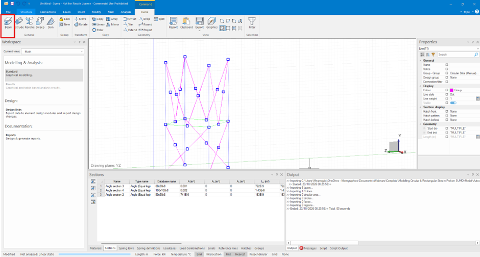
- Assign the appropriate material and cross-section properties, and check connectivity at member intersections.
Cylindrical Wall
- Use the wall object with a thickness of 75 mm and a target mesh size of 0.25 m.
- Create the initial wall segment.
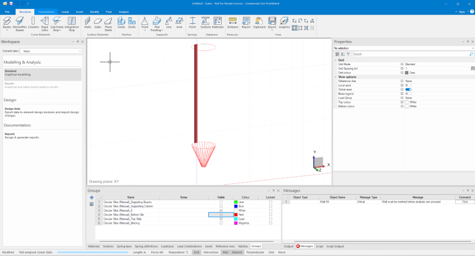
- and use the polar-copy workflow to generate the remaining sections around the silo axis
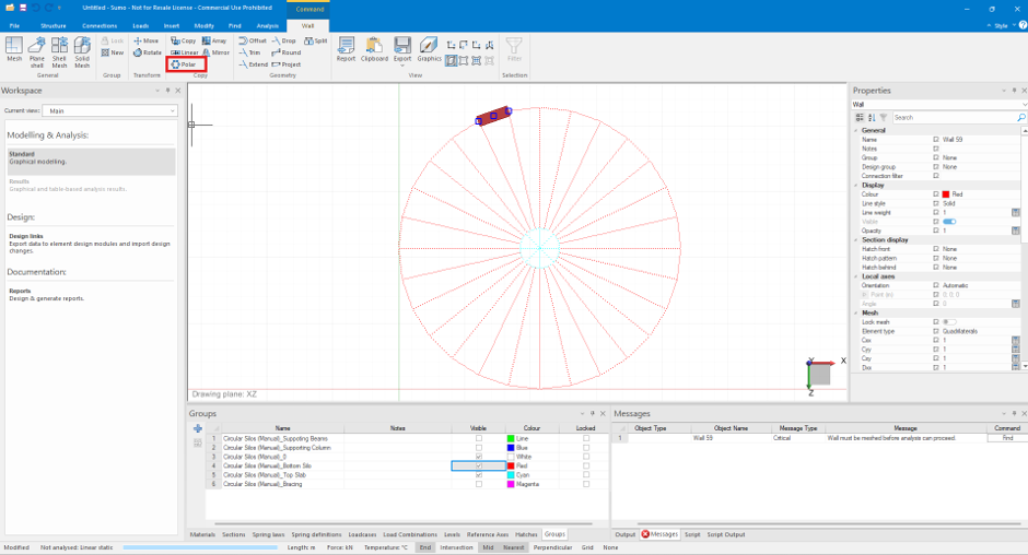
- Once the wall is copied, the wall should be complete.
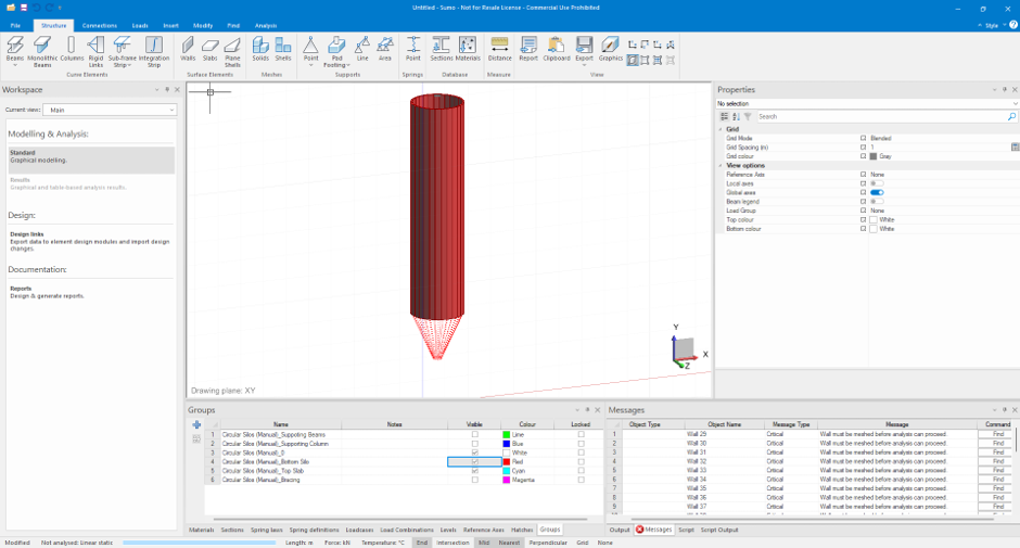
Conical Hopper
- Represent the inclined hopper surfaces using plane shells.
- Create the initial section
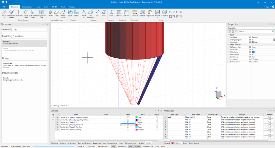
- and use polar copying to complete the conical geometry.
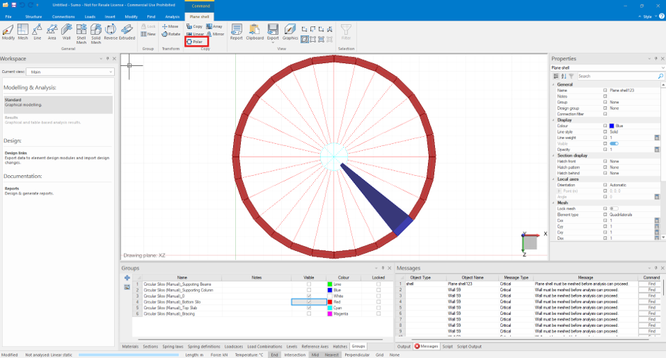
- Once the plane shell is copied, the hopper should be complete.
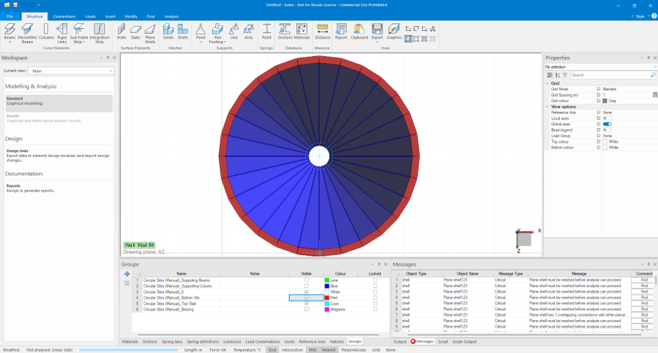
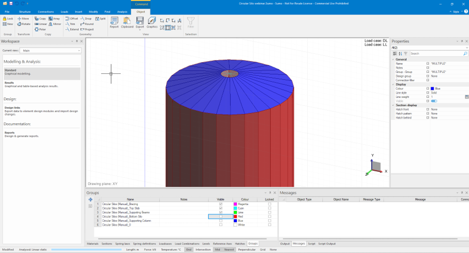
Top Slab
- Use Plane shells to represent the roof or top slab.
- Create the required shell geometry and use the appropriate copying or modelling workflow to complete the surface.
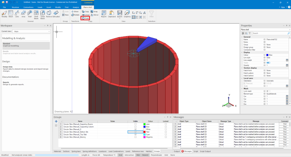
- Once the plane shell is copied, the hopper should be complete.
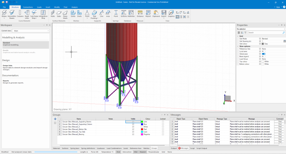
Assigning Supports
At the base of the supporting column, assign fixed supports or pinned supports, depending on the foundation design.
- For steel silo bolted to concrete pedestals → use pinned supports.
- If the base is embedded in a reinforced concrete block → use fixed supports.
Use Supports → Fixed/Pinned from the ribbon or right-click menu.
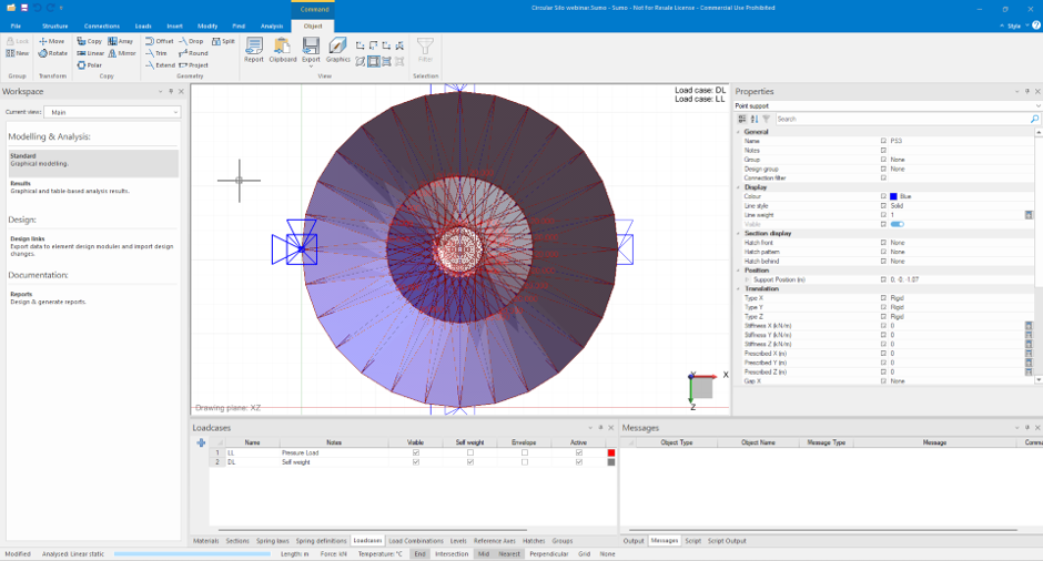
Applying Loads to the Circular Silo
One of the most important aspects of silo modelling is understanding how the stored material interacts with the structure.
Unlike a conventional building where loads may be relatively straightforward, silo loading can involve both vertical and horizontal pressures.
Depending on the design situation, relevant loads may include:
- Self-weight
- Stored material weight
- Vertical pressure
- Lateral pressure
- Roof loads
- Wind loads
- Equipment loads
- Maintenance loads
- Temperature effects, where applicable
For a circular silo, lateral pressure acting on the cylindrical wall generates circumferential forces in addition to bending and other local effects.
The magnitude and distribution of stored-material pressures should be established using the applicable design standard and the relevant material and operating conditions. These pressures should then be represented appropriately in the model.
Running the Analysis and Reviewing results
Before running the analysis, check the model for connectivity, support restraints, element orientation, material properties, load application, mesh quality and overall stability.
Once the model has been verified, run the analysis and review the structural response.
Important results include:
- Deformations
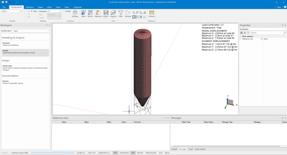
- Support reactions
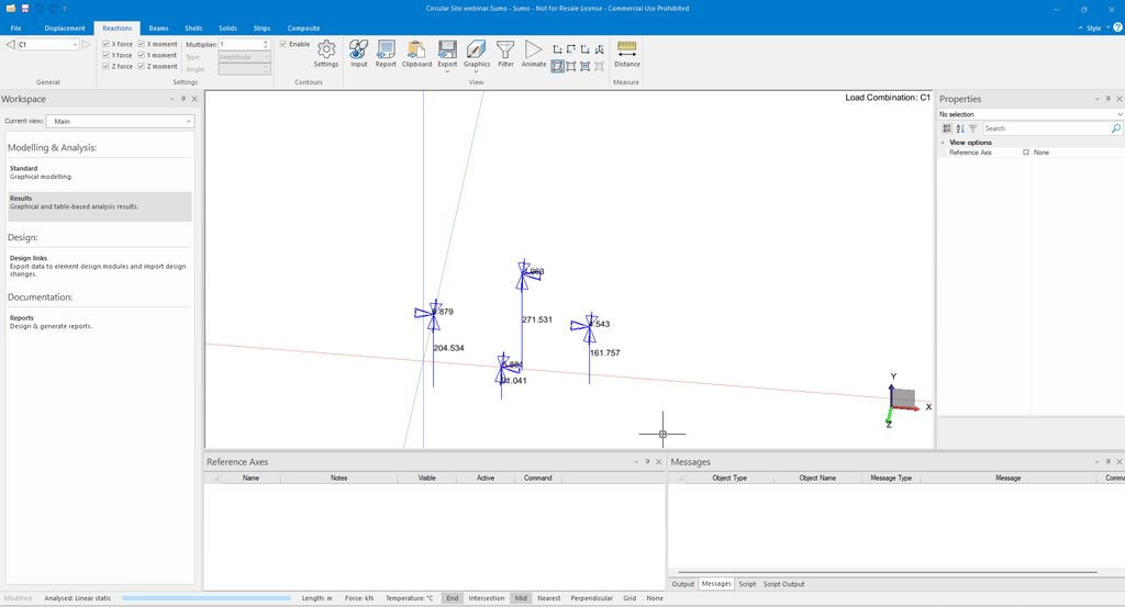
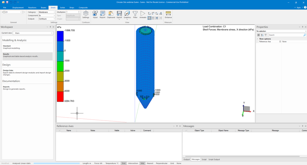
- Membrane forces
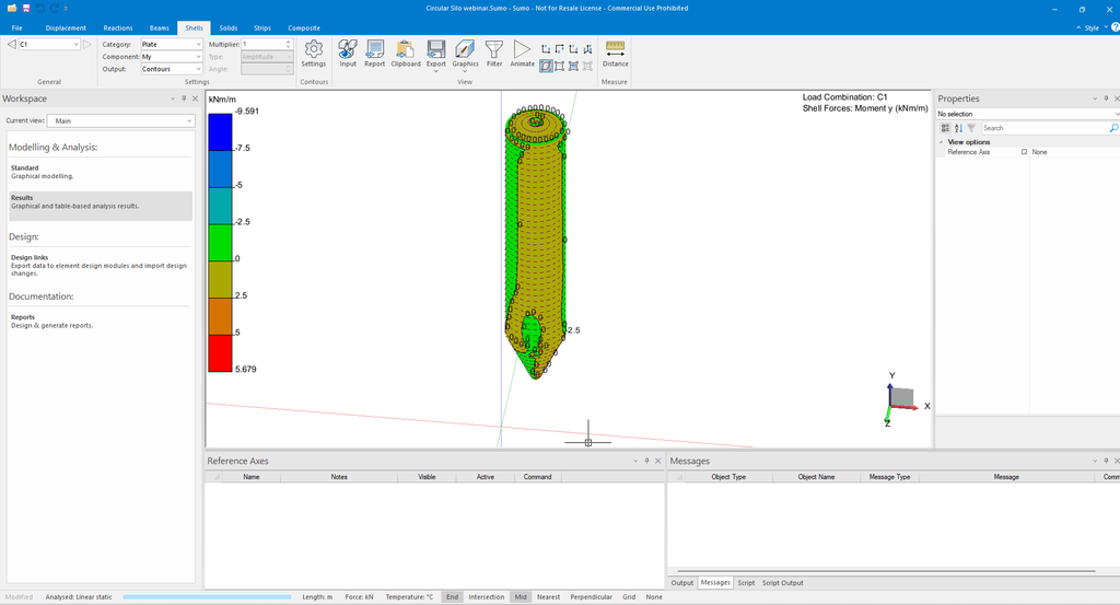
- Bending moments
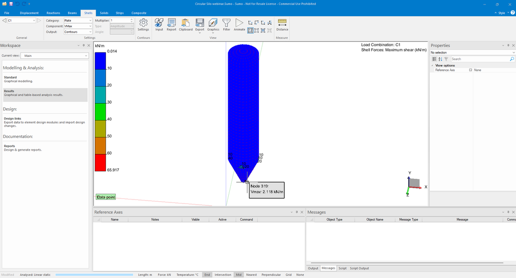
- Shear forces
- Stresses
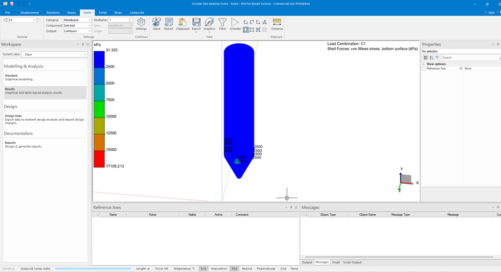
Pay particular attention to the distribution of forces around the cylindrical wall, as well as the wall-to-base connection, hopper transition and supporting frame.
The results should be interpreted in the context of the applied loads, boundary conditions and intended structural behaviour.
Modelling a Rectangular Silo in SUMO
The modelling process for a rectangular silo follows a similar workflow, but its flat wall panels introduce different structural considerations.
Model Setup
Pay particular attention to the distribution of forces around the cylindrical wall, as well as the wall-to-base connection, hopper transition and supporting frame.
The results should be interpreted in the context of the applied loads, boundary conditions and intended structural behaviour.
Modelling a Rectangular Silo in SUMO
The modelling process for a rectangular silo follows a similar workflow, but its flat wall panels introduce different structural considerations.
1. Model setup
The example rectangular silo uses the following dimensions:
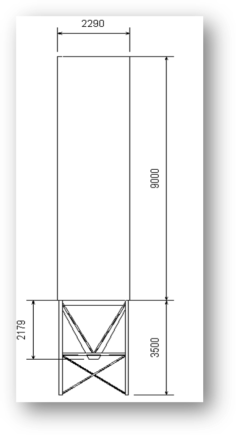
Typical parameters include:
- Width=2.290m
- Height= 9m
- Wall thickness= 150mm
- Base slab thickness=150mm
The remaining dimensions, including the length, support arrangement and hopper geometry, should be established from the design drawings where applicable.
Importing DWG into Prokon SUMO
- Import the DWG drawing through File → Import → DWG.
- Configure the import units and options.
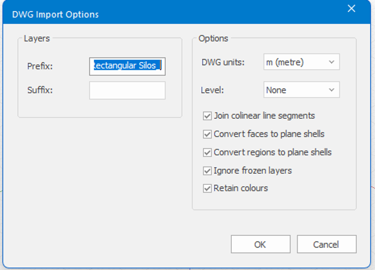
- Review the resulting geometry and groups
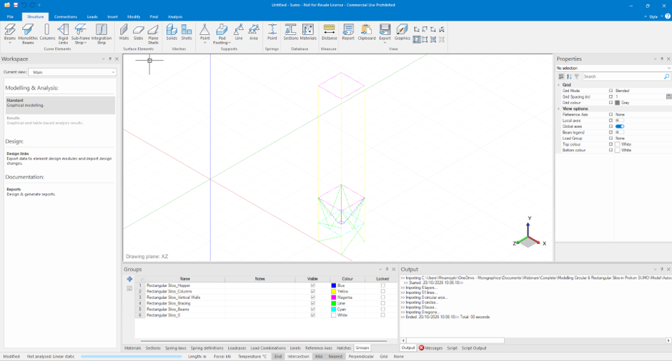
Defining Materials and Sections
- Populate the materials table with the appropriate structural steel and concrete materials.
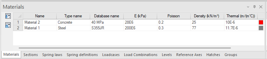
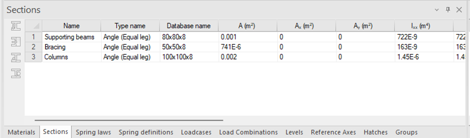
- Define the supporting steel sections using the same specified profiles as the circular example:
- Column = 100x100x8 A1
- Supporting Beams= 80X80X8 A1
- Bracing = 50X50X8 A1
Building the Structural Model
Supporting frame
- Convert the imported curves into beams and columns, using groups to isolate the relevant structural lines.
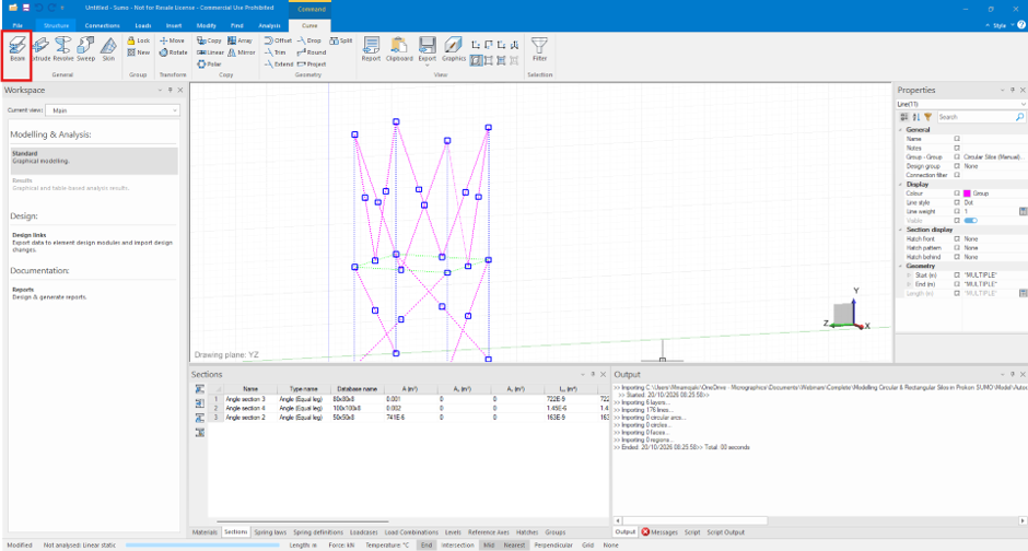
- Assign the appropriate material and section properties, and verify connectivity at member joints.
Walls.
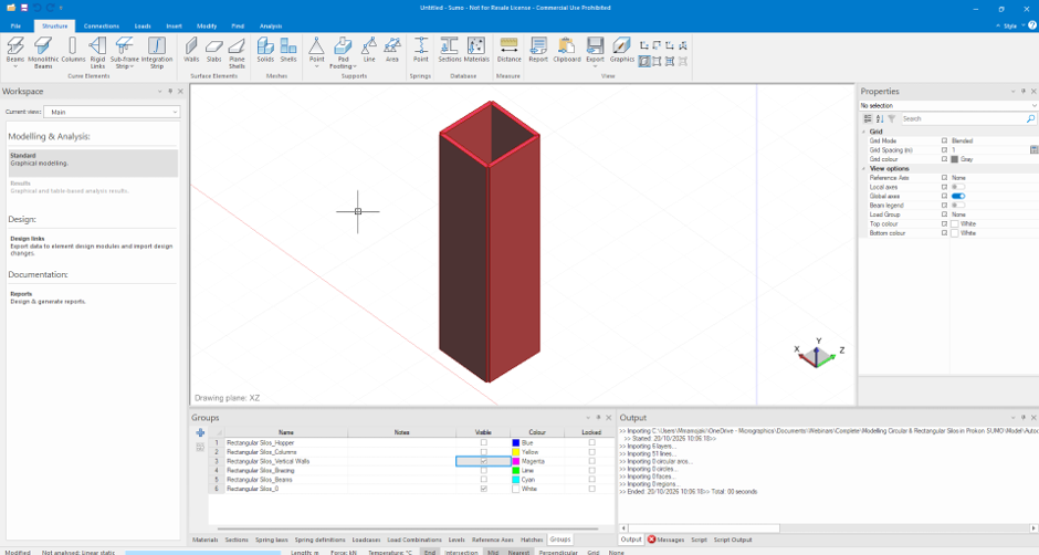
- Use wall objects to represent the 150 mm concrete walls, with a target mesh size of 0.25 m.
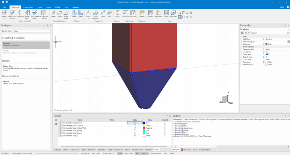
Hopper
- Where an inclined discharge section is included, use plane shells to represent its surfaces.
- Ensure that the hopper connects correctly to the walls and base or supporting structure.
Base and Roof slabs
- Include these components where required by the actual configuration. Represent their thicknesses, material properties and connections accurately.
Pay particular attention to wall intersections, wall-to-base connections and changes in geometry, as these can significantly affect the resulting forces and deformations.
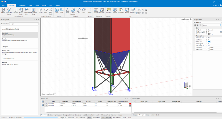
Assigning Supports
Assign fixed or pinned supports at the bases of the supporting columns according to the intended foundation and connection details.
Applying Loads to a Rectangular Silo
The load cases for a rectangular silo may include:
- Vertical loads: Self-weight and loads transferred from the stored material.
- Lateral loads: Pressure exerted by the stored material on the internal wall surfaces.
- Environmental loads: Wind and other relevant environmental actions.
- Additional loads: Roof, equipment and maintenance loads, where applicable.
The lateral pressure distribution should be established from the relevant design requirements and applied to the appropriate wall surfaces.
Unlike a circular silo, a rectangular silo relies more heavily on the bending and shear resistance of its flat wall panels. Internal dividing walls, where present, may also influence how the loads are transferred through the structure.
Establish appropriate load combinations for the relevant design situations before evaluating the results.
Analysis & Results
After checking connectivity, supports, material properties, loading and mesh quality, run the analysis and review:
- Wall and slab deflections
- Bending moments and shear forces
- Membrane forces
- Support reactions
- Stress distribution
Give particular attention to corners, wall intersections, wall-to-base connections, openings, hopper transitions and support points.
These locations may experience increased structural demand and require further investigation during design.
Circular vs. Rectangular Silos
Although both silo types perform the same basic function, their structural behaviour is significantly different.
| Circular Silo | Rectangular Silo |
| Curved cylindrical walls | Flat wall panels |
| Significant circumferential/hoop action | Greater reliance on plate bending |
| Pressure is distributed around the circumference | Pressure is resisted primarily by individual wall panels |
| Generally efficient for uniform pressure | Corners and wall connections require particular attention |
| Geometry can provide efficient load distribution | Internal walls can influence load transfer significantly |
Understanding these differences helps engineers develop analytical models that better represent the actual structural system.
Why Structural Modelling Matters
A structural model is more than a geometric representation of a silo. It helps engineers investigate how the structure responds to different loading conditions and identify areas that may require further attention.
A well-developed SUMO model can help engineers:
- Visualise structural behaviour
- Investigate load paths
- Evaluate deformations and internal forces
- Identify critical regions
- Compare alternative structural configurations
- Support informed engineering decisions
However, the reliability of the results depends on the quality of the geometry, material properties, boundary conditions, loading assumptions and modelling approach.
Structural analysis in SUMO should form part of the overall engineering design process, not replace the necessary design checks. The analysis results must be assessed against the applicable design standards and verified for the relevant strength, stability, serviceability and foundation requirements.
Conclusion
Modelling circular and rectangular silos in PROKON SUMO requires careful consideration of geometry, structural connectivity, material properties, loading and support conditions.
Circular silos develop significant circumferential forces through their curved walls, while rectangular silos rely more heavily on the bending and shear resistance of their flat panels and connections.
By following a structured workflow – from importing geometry and defining structural elements to applying loads, running the analysis and reviewing results – engineers can develop useful analytical models and gain a clearer understanding of silo behaviour.
Ultimately, the objective is to create a reliable structural model that represents the intended load-transfer mechanism and provides meaningful information for the engineering design process.
