

Both Member Design for Combined Stress (COMBINE) and Member Design for Strut modules in Prokon assess the strength and stability of structural members. However, they serve different loading conditions, design objectives, and structural applications.
Both modules support two design modes:
- Interactive Mode – Manually design for Members
- Post-Processing – Export from Prokon SUMO/ Frame Analysis.
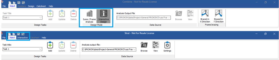
Below is a detailed comparison:
Purpose
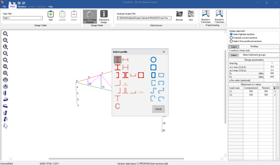
Member Design for Combined Stress
- Application: Used for designing structural members subjected to axial stress (compression/tension) combined with bending moments about one or both axes. Supports non-symmetric sections (e.g., angles) based on the selected design code.
- Typical Scenarios Cases: Columns, eccentrically loaded beams, or members subjected to both vertical and lateral forces.
- Design Focus: Evaluates combined axial and bending stress to ensure safety based on interaction equations.
Member Design for Strut
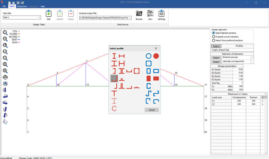
- Application: Designed for steel members under axial stress.
- Typical Use Cases: Bracing members, light posts, or other columns prone to buckling.
- Design Focus: Prevents buckling failure by calculating critical slenderness ratios and evaluating stability under axial compression.
Key Design Parameters
Member Design for Combined Stress
- Load Considerations: Axial forces + bending moments (Mx and My).
- Stress Interaction: Uses interaction equations to evaluate combined axial and bending stresses
- Capacity Check: Ensures that combined stress does not exceed member strength, based on interaction diagrams.
Member Design for Strut
- Load Considerations: Axial compression only.
- Buckling Check: Prevents buckling failure by calculating critical slenderness ratios and evaluating stability under axial compression.
- Capacity Check: Ensures the strut remains stable under axial compression and critical buckling load is not exceeded.
Governing Design Codes
Both modules align with structural design codes such as Eurocode, SANS, or ASCE.
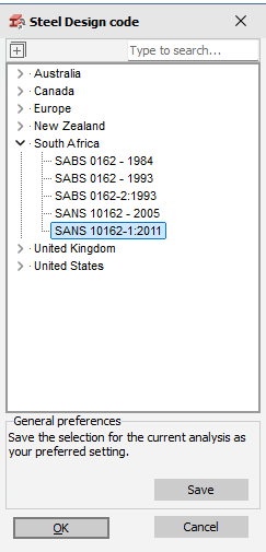
However:
- Combine → Includes axial + flexural provisions from the code.
- Strut → Focuses on axial compression + buckling provisions.
Input Requirements
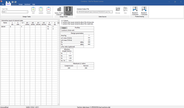
Member Design for Combined Stress
- Geometry: Member length, cross-section properties, end conditions.
- Loads: Axial load (P), moments (Mx, My).
- Material Properties: Elastic modulus, yield stress.
- Boundary Conditions: Support conditions affecting bending and axial loads.
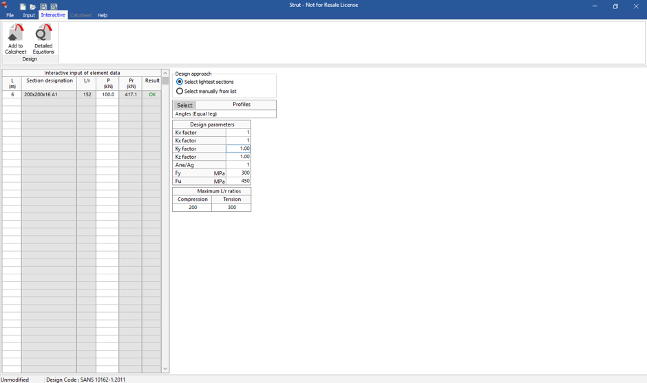
Member Design for Strut
- Geometry: Effective length factor, slenderness ratio.
- Loads: Axial compression load only.
- Material Properties: Elastic modulus, yield stress.
- Boundary Conditions: Buckling length and effective end restraints.
Design Output
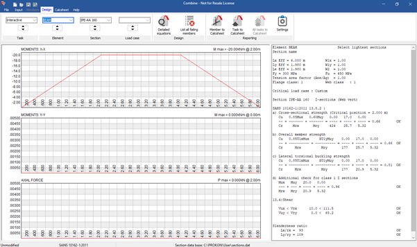
Member Design for Combined Stress
- Combined stress ratios for axial and bending forces.
- Interaction diagram for stress distribution.
- Recommendations for resizing or reinforcing members if overstressed.
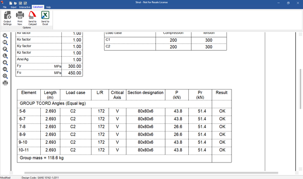
Member Design for Strut
- Critical buckling load and safety factor.
- Slenderness ratio and stability check.
- Warnings about insufficient buckling resistance.
Limitations
Member Design for Combined Stress
- Not ideal for members primarily governed by buckling.
- Does not explicitly calculate critical buckling loads.
Member Design for Strut
- Ignores bending moments; applicable only to axially loaded compression members.
- Limited for members experiencing lateral loads or eccentricity.
Conclusion
- Use Member Design Combined Stress when the member is subjected to both axial loads and bending moments, as it evaluates their combined effects on member capacity.
- Use Member Design Strut for members under pure axial compression where buckling stability is the primary concern.
Understanding the difference between these modules ensures that the correct tool is used for specific design scenarios, improving both accuracy and efficiency in structural design.
