

The Composite Continuous Beam Design module in PROKON is used to design multi-span composite beams, where each span may consist of one or more sections. The module performs design checks for:
- Sagging moments
- Hogging moments
- Shear resistance
- Deflection behaviour
- Composite interaction between steel and concrete

Code of Practice Support
The module currently supports only:
- Eurocode 4 — EN 1994-1-1:2004
The software also allows importation of country-specific National Annex parameters for localized design requirements.
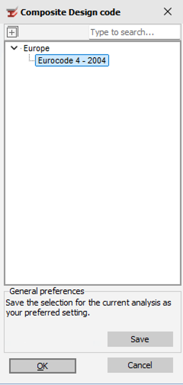
The fundamental input parameters
The module requires the following primary inputs:
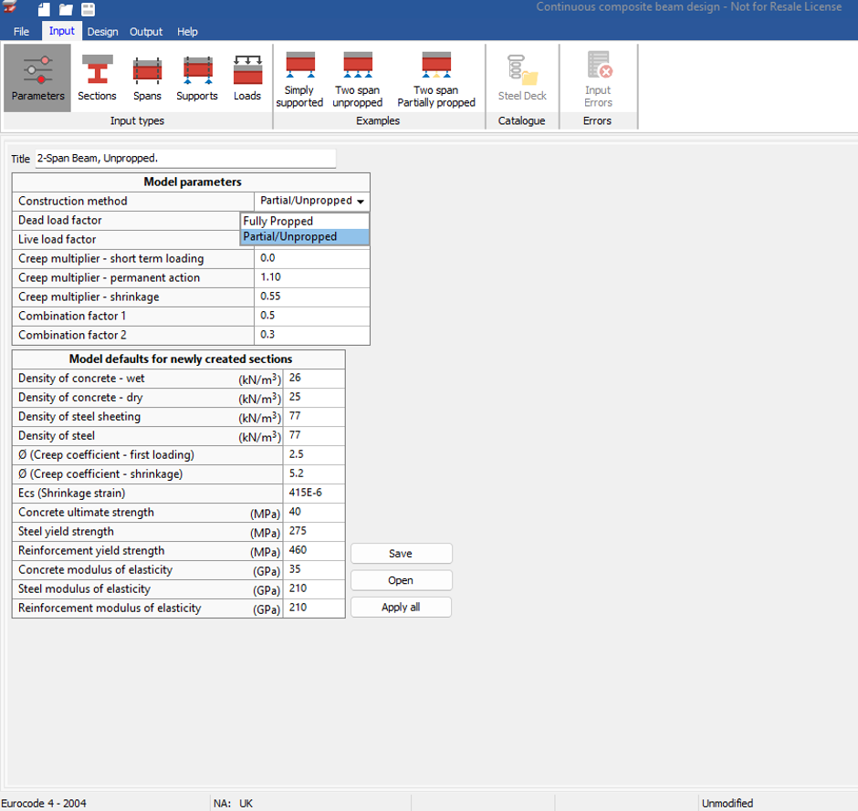
Model Parameters:
- Construction Method
- Two construction methods are available:
- Partial/unpropped: During construction the steel section is not supported and must resist dead weight of wet concrete. The steel section is stressed and deflects.
- Fully Propped: During Construction the steel section is supported on temporary proper and does not have to resist significant bending moments.
- Two construction methods are available:
- Load Factors:
The module allows definition of:
- Dead load factors
- Live load factors
- Creep Parameters
The following creep multipliers are available:
| Parameter | Typical Value |
| Short-term loading creep multiplier | 1.0 |
| Permanent action creep multiplier | 1.0 |
| Shrinkage creep multiplier | 0.55 |
- Combination factors as per the specified design code
- Combination Factor1 – applied to the variable action Q1 in the Frequent combination
- Combination Factor 2 – applied to the variable action Q1 in the Quasi-permanent combination
Combination Factors
According to Eurocode EN 1990, three combinations are used.
| Combination | Formula |
| Characteristic | Gk + Q₁ |
| Frequent | Gk + (Ψ₁ × Q₁) |
| Quasi-permanent | Gk + (Ψ₂ × Q₁) |
Where:
- Gk = Characteristic Permanent Action
- Q₁ = Characteristic Variable Action
- Ψ₁ = Combination Factor 1
- Ψ₂ = Combination Factor 2
Eurocode Combination Types
Characteristic Combination
Used for:
- Irreversible limit states
- Ultimate limit state verification
Frequent Combination
Used for:
- Reversible limit states
- Elastic deflection checks
Quasi-Permanent Combination
Used for:
- Long-term effects
- Creep
- Shrinkage calculations
Model defaults for newly created sections
- Density of Wet concrete
- Density of Concrete- Dry
- Density of steel sheeting
- Density of steel
- Creep Coefficient – loading
- Creep Coefficient -shrinkage
- Shrinkage Strain
- Concrete Ultimate strength
- Reinforcement Yield Strength
- Concrete Modulus of Elasticity
- Reinforcement Modulus of Elasticity
The module allows you to save load and apply all model defaults for any newly constructed sections along the length of the composite beam.
Section Definition
The Section tab is similar to the standard Composite Beam module, but additionally allows:
- Actual slab width definition
- Multiple section definitions along the beam
- Different sections for:
- Hogging regions
- Sagging regions
The module also calculates equivalent line loads for:
- Concrete
- Temporary formwork
- Steel beam self-weight
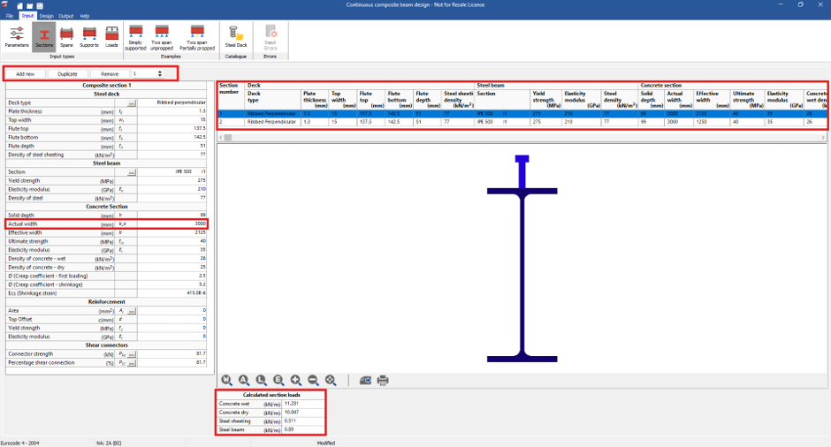
- Deck Configuration
You may choose:
- No deck
- Flat deck
- Ribbed deck:
- Parallel to beam
- Perpendicular to beam
- Corrugated deck:
- Parallel
- Perpendicular
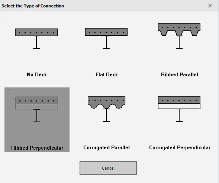
The module provides a dimensional sketch reference to guide correct input of deck dimensions.
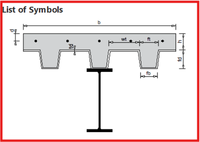
- Top width
- Flute Top
- Flute Bottom
- Flute Depth
- Density of steel sheeting
Steel Beam
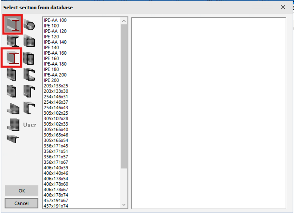
- Section Selection
- The module supports:
- Standard I-sections and H-section if you have selected the South African Code of Practice
- Concrete Section Definition
- Slab Parameters
- You must define:
- Slab thickness
- Actual Width: the tributary width.
- Effective width (as per code guidelines)
- You must define:
- Slab Parameters
The effective width is calculated according to Eurocode provisions for composite action.
- Reinforcement
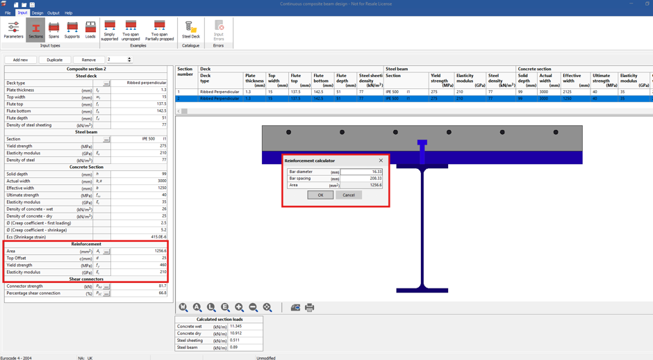
- The following are available to define the reinforcement:
- Enter the area of reinforcement directly, or
- Input:
- Bar diameter
- Bar spacing
- The following are available to define the reinforcement:
The module will then automatically calculate the area of steel provided.
- Shear Connectors
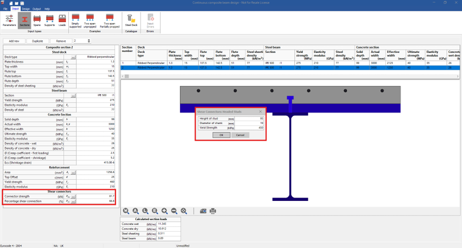
- Shear connection is provided to transmit the longitudinal shear force between the concrete and the structural steel element. Ignoring the effect of natural bond between the two elements.
- You have two options:
- Manual Strength Input
- If product-specific technical data is available, you can:
- Enter the connector strength directly
- If product-specific technical data is available, you can:
- Automatic Calculation
- Specify:
- Shank height
- Diameter
- Yield strength
- Specify:
- Manual Strength Input
The module calculates connector resistance according to the code selected.
- Percentage Shear Connection
- You may:
- Specify a percentage shear connection, or
- Enter the number of shear connectors, and the module will determine the percentage connection per code requirements.
- You may:
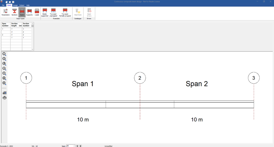
Span Definition
The Spans tab allows:
- Multiple spans
- Different section assignments
- Variable section lengths
- Section positioning along the beam
This enables accurate modelling of:
- Hogging regions
- Sagging regions
- Variable composite sections
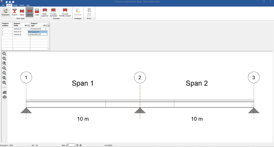
Support Definition
The module supports different support fixities:
| Support Type |
|---|
| Vertical fixed |
| Pinned |
| Construction support |
| Permanent support |
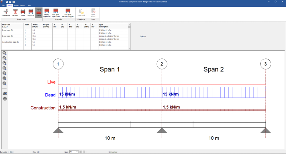
Load Definition
The Loads tab allows:
Load Cases
- Dead loads
- Live loads
- Construction loads
Load Types
- Line loads
- Point loads
- Applied moments
Loads can be positioned anywhere along the beam length.
Summary of Design Results
The Design tab provides:
- Tabular summaries
- Graphical summaries
- Utilization ratios
- Critical force locations
- Failure mechanism identification
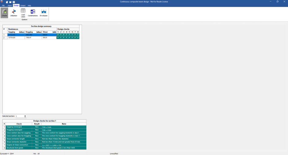
Design Checks
The Checks tab summarizes:
- Code compliance
- Pass/fail results
- Section-by-section verification
- Construction stage checks
- Composite stage checks
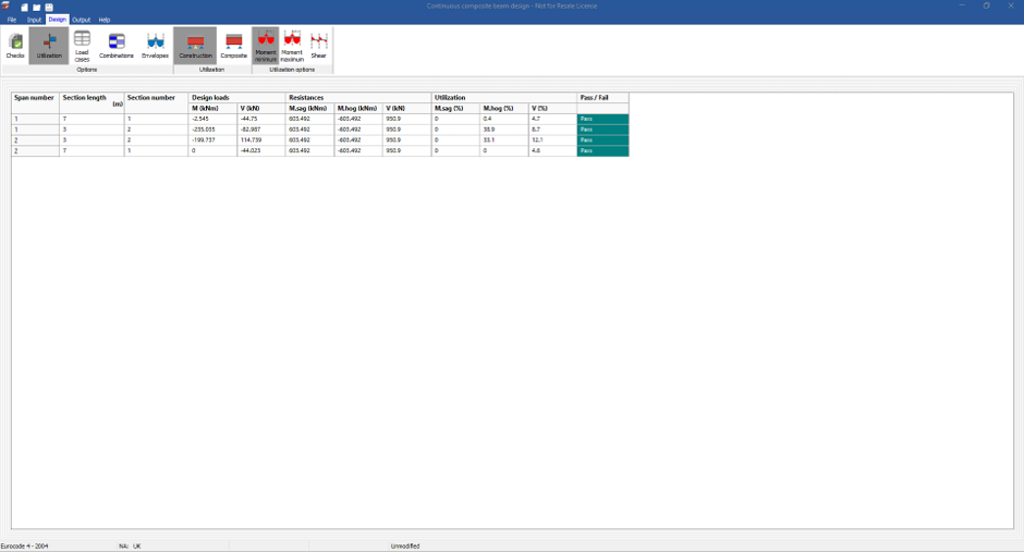
Utilisation Results
The Utilisation tab displays:
| Result Type |
|---|
| Maximum moments |
| Minimum moments |
| Shear utilisation |
| Resistance values |
For unpropped construction, both:
- Construction stage results
- Composite stage results
can be reviewed independently.
Loadcases, Combinations and Envelopes
The module provides:
- Deflection diagrams
- Moment diagrams
- Shear force diagrams
- Load envelopes
- Combination results
for all:
- Load cases
- Combinations
- Span regions
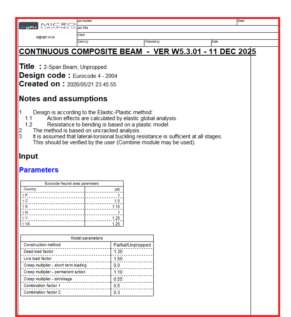
Calculation Sheet (Calcsheet)
The Calculation Sheet provides detailed transparent calculations including:
Project-Specific Parameters
- Steel section properties
- Slab dimensions
- Reinforcement
- Shear connectors
- National Annex parameters
Design Results
- Construction utilization checks
- Composite utilization checks
- Design diagrams
- Shear connection calculations
Benefits of the Module
The module provides:
- Transparent calculations
- Code traceability
- Submission-ready documentation
- Composite beam optimization
- Multi-span design capability
- Construction stage verification
