

Power transmission pylons are critical structures in the energy sector, supporting overhead power lines and ensuring safe and efficient electricity transmission over long distances.
Designing and analysing these tall, slender steel frameworks requires both accuracy and flexibility — this is where Prokon SUMO becomes a powerful tool.
SUMO provides a 3D finite element modelling environment where engineers can simulate structural behaviour, apply loads, and check member performance based on design codes.
In this guide, we’ll explore how to model a power transmission pylon in Prokon SUMO, step-by-step.
Understanding the Structure
Before starting in SUMO, it’s important to understand the key components of a power transmission pylon:
- Main legs (vertical members): Provide overall height and stability.
- Bracings (diagonal and horizontal): Transfer loads and maintain rigidity.
- Top platform/cross arm: Supports the conductors.
- Base connections: Anchor the structure to the foundation.
Most pylons are space trusses — meaning they carry loads through triangulated members connected at joints.

Importing DWG into Prokon SUMO
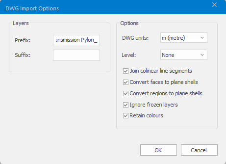
- File → Import → DWG.
- Edit the DWG Import Options: Select the geometry and units (from AutoCAD).
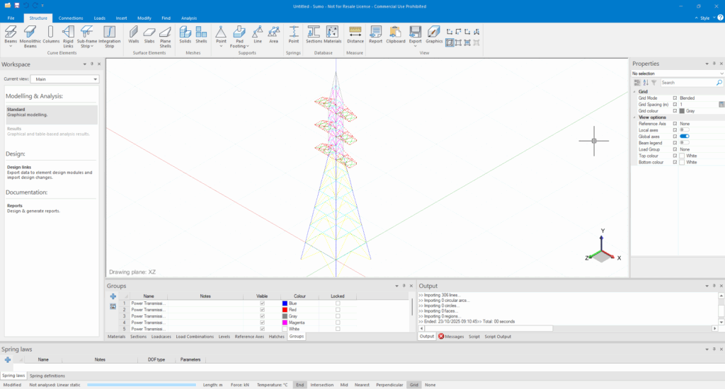
- Layers from AutoCAD become SUMO groups
Populating the Sections and Materials Table
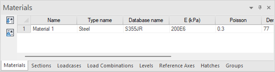
- Add Material: Structural Steel (e.g., S355 or equivalent).
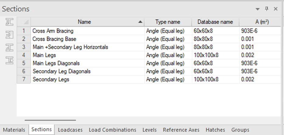
- Define Sections under the Sections Table → Choose relevant shapes:
- Angle Sections (L) for bracings
- Tubular Sections (CHS) or Angle Sections (L) for legs
- Plates or channels for top arms or connections
Building the Structural Model
Converting Curves into Beams and Columns
- Convert curves to Beams/Columns
- Use Groups to isolate structural lines
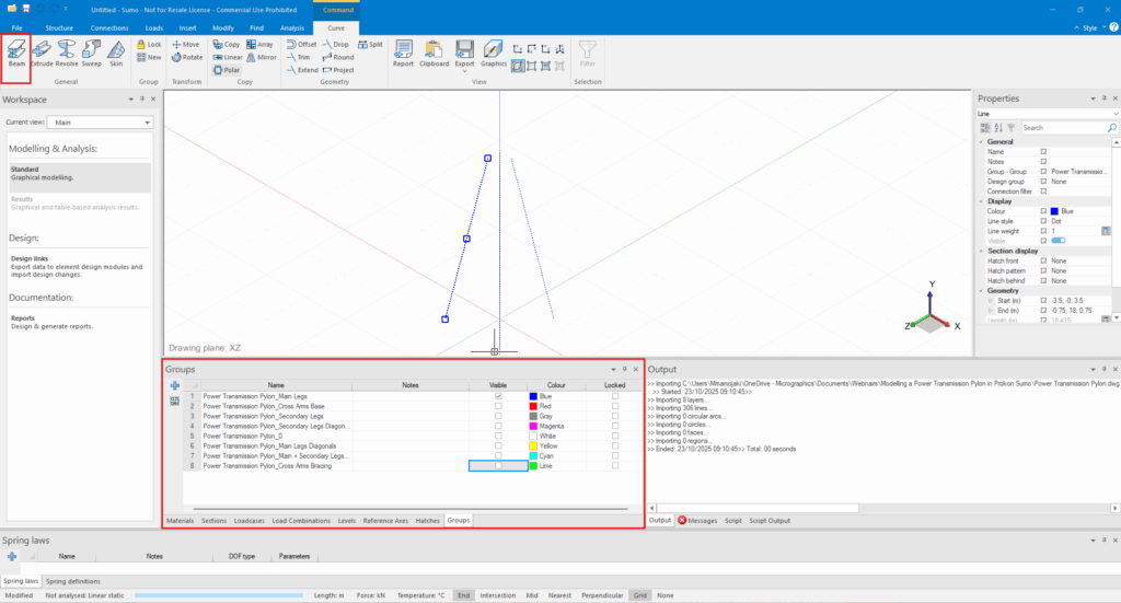
- Assign cross-sections and material properties.
- Ensure connectivity between members at joints.
- Model main legs, bracings, cross arms and horizontal members.
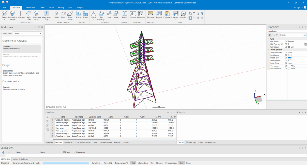
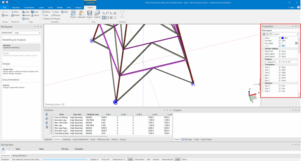
Assigning Supports
- At the base of the pylon, assign fixed supports or pinned supports, depending on the foundation design.
- For steel towers bolted to concrete pedestals → use pinned supports.
- If the base is embedded in a reinforced concrete block → use fixed supports.
Assigning Loads to Structural Elements
Transmission pylons are subject to several load types:
- Dead Loads: Self-weight (automatically included if material density is defined).
- Live Loads: Maintenance or installation loads.
- Wind Loads: Apply using distributed area loads or nodal forces.
- Cable Loads: Represented as horizontal and vertical forces at the top nodes (cross-arm level).
In SUMO:
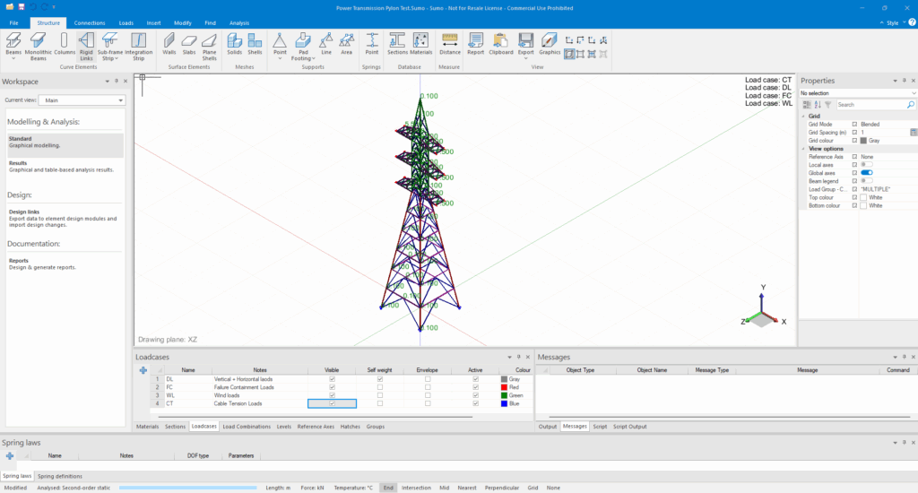
- Create a Load Case for Wind, one for Dead, Failure Containment and one for Cable Tension on the inputs Table.
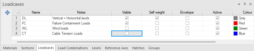
- Assign loads to cable loads on anchor points and to structural elements.
Running the Analysis
After defining the geometry, materials, and loads:
- Check model connectivity (no unjoined nodes or unstable members).
- Use Run Analysis to perform a linear static analysis.
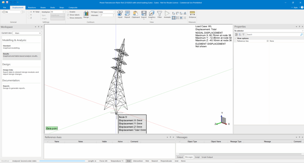
- Review the Deformed Shape to confirm realistic structural behaviour.
Reviewing Results and Output
After analysis:
- Use Results → Member Forces to check axial and shear forces.
- View Deflections to assess lateral stiffness.
- Export to Design Links → Steel Member Design to check member adequacy per your design code (e.g., SANS 10162, EN 1993).
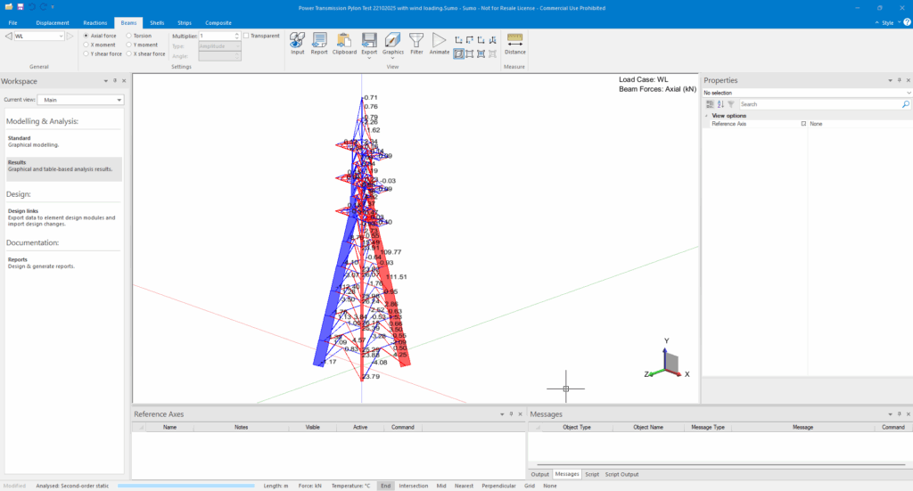
You can also export bending moments and forces for report documentation.
Refining and Validating the Model
Iterate your design:
- Adjust bracing configuration if deflections are excessive.
- Optimize member sizes using Member Design Link feedback.
- Validate results with Load Path Checks and Wind Pressure Sensitivity.
Conclusion
Prokon SUMO simplifies the modelling and design of Power Transmission Pylons, offering a complete workflow from geometry to detailed design validation
