

Introduction
A box culvert is a reinforced concrete structure commonly used to convey water beneath roads, railways, or embankments. It consists of a rigid rectangular frame formed by:
- A Base Slab
- Vertical side walls
- A Top Slab.
Key Applications
Box culverts are widely used in:
- Road and railway drainage systems
- Stormwater management infrastructure
- Canal and watercourse crossings
- Pedestrian and service tunnels
Modelling Overview in Prokon SUMO
In Prokon SUMO modelling involves:
- defining structural elements
- Assigning material properties
- Adding supports and boundary conditions
- Simulating realistic loading scenarios
This guide outlines a structured workflow for accurate modelling and analysis of Box Culvert in SUMO.
Understanding the Structure
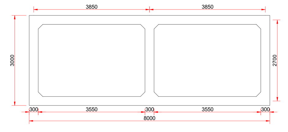
Before modelling, define the culvert geometry:
| Component | Dimension / Property |
| Top Slab | 300 mm thick |
| Base Slab | 300 mm thick |
| Side Walls | 3 m high, 300 mm thick |
| Wing Walls | 3 m high, 2.85 m wide, 300 mm thick |
Importing DWG into SUMO
- Navigate to File → Import → DWG.
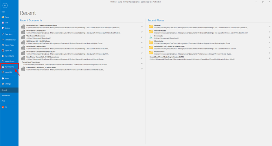
- Select the DWG file containing the culvert geometry.
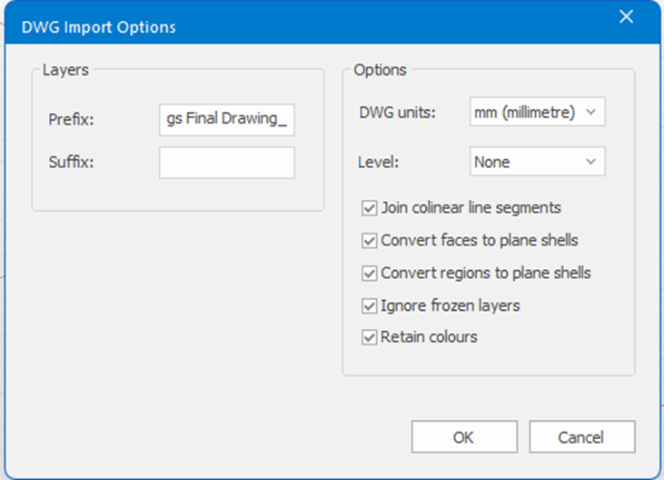
- Ensure the scale and units are correct.
- Clean up unnecessary layers and lines if needed.
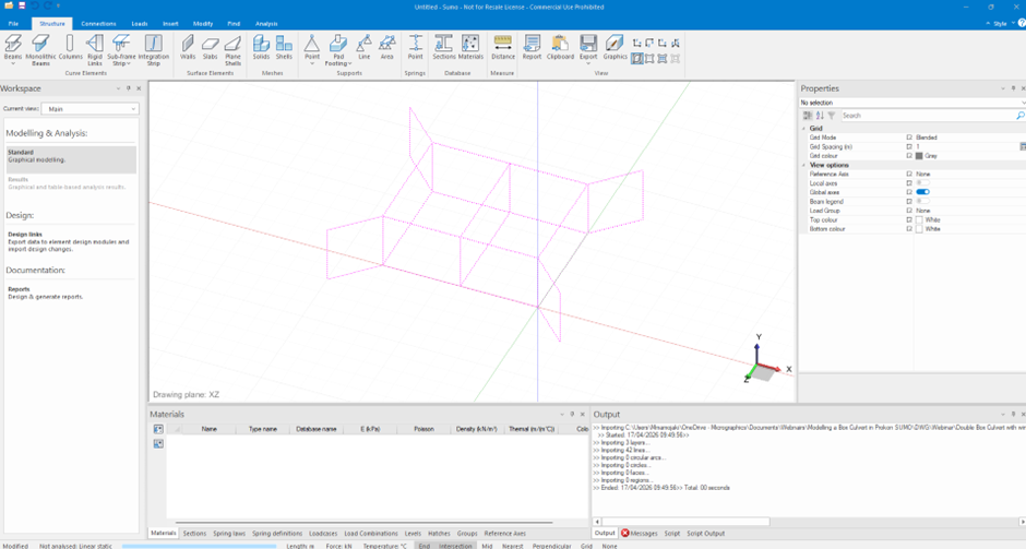
- Use the imported geometry as a modelling reference only.
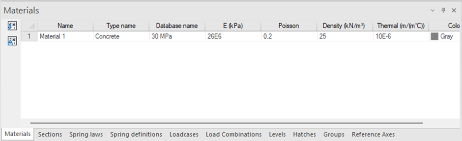
Populating Materials Table
- Define concrete grade (30MPa).
Modelling the Structural Elements
Plane Shell Elements
Used for:
- Culvert opening
Steps:
- Draw outlines using curves
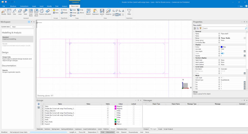
- Trace geometry.
- Properties:
- Thickness: 300mm
- Mesh size: 0.25m
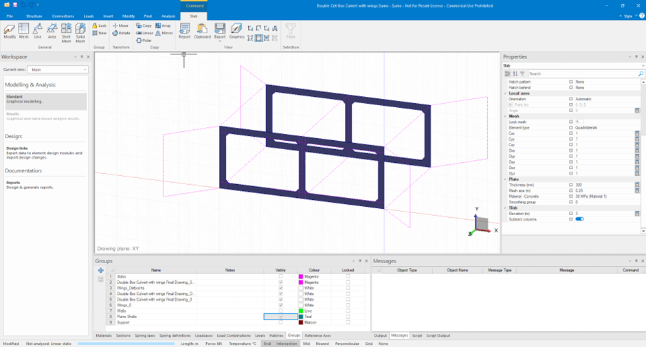
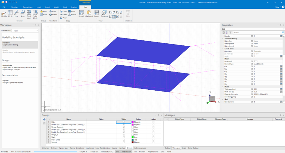
Slabs
Used for:
- Top Slab
- base Slab
Properties:
- Thickness: 300mm
- Mesh size: 0.25m
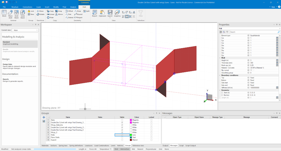
Walls
Used for:
- Side walls
- Wing walls
Properties:
- Thickness: 300mm
- Mesh size: 0.25m
Boundary Conditions:
- Top: Fixed
- Bottom: Fixed
- Side start and end: Fixed
Adding Supports to the Model
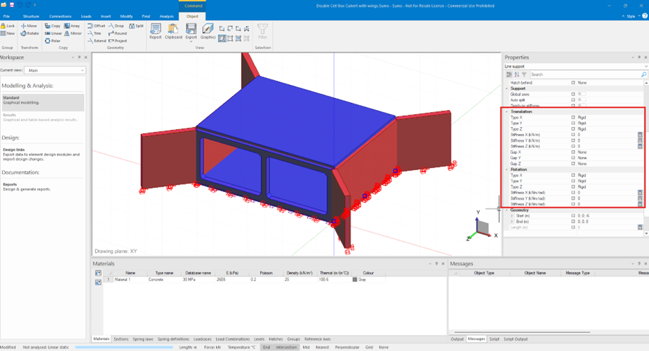
- Define supports at the base of the culvert:
- Fixed supports for rigid foundation assumptions.
- Spring supports if modelling soil-structure interaction.
- For realistic modelling:
- Use area supports to simulate soil stiffness.
Assigning Loads
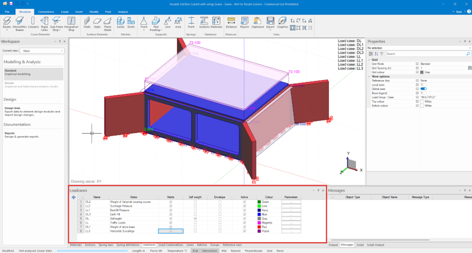
Apply relevant loads, including:
Dead Loads
- Self-weight (automatically included if enabled).
- Additional permanent loads (e.g., road layers).
Live Loads
- Traffic loads applied on the top slab.
- Load distribution based on design standards.
Earth Pressure
- Lateral loads applied to side walls.
- Consider:
- at-rest pressure
- active pressure
- passive earth pressure conditions.
Hydrostatic Pressure
- Applied to walls and base slab if water is present.
Load Combinations
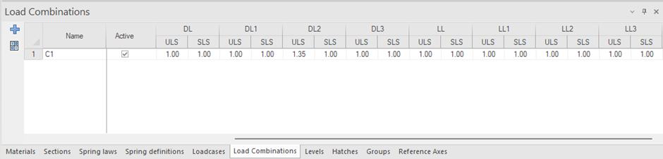
- Define load combinations according to relevant design codes.
- Ensure inclusion of:
- Ultimate Limit State (ULS)
- Serviceability Limit State (SLS)
Run an Analysis
- Select the appropriate analysis type:
- Linear static analysis for basic evaluation.
- Non-linear or second-order analysis if required.

- Run the analysis.
- Check for errors or warnings:
- Instability issues
- Unconnected nodes
- Load application errors
Accessing Output
Review analysis results, including:
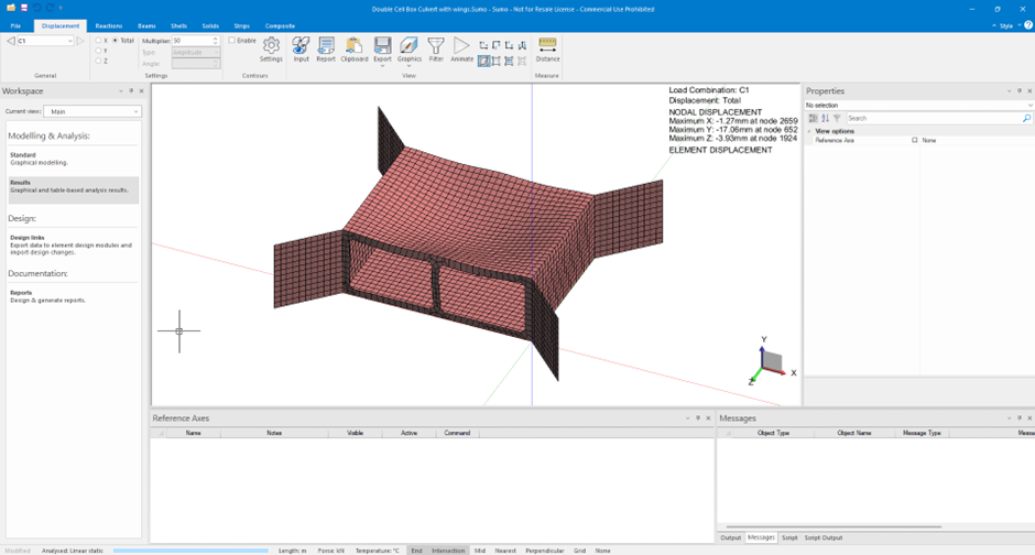
- Displacements:
- deflection of slabs and walls
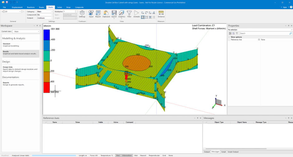
- Bending moments (Mx, My)
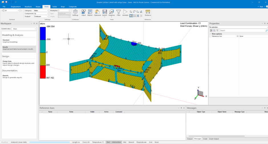
- Shear forces
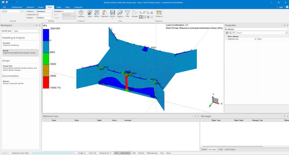
- Stress distribution in shell elements
Visualisation Tools
- Contour plots
- Force diagrams
- Deformed shape views
Conclusion
- Prokon SUMO simplifies the modelling and design of Box Culvert, offering a complete workflow from geometry to detailed validation.
- Accurate modelling of a box culvert in Prokon SUMO depends on:
- Proper geometry definition
- Realistic support conditions
- Correct load application
- Ensuring full connectivity of elements
- A well-constructed model leads to reliable and design-ready results.
- Loads and combinations govern design.
Was this helpful?
Thanks for your feedback!
