

Shear walls in Prokon SUMO are best modelled using Wall Tool, which applies shell elements for accurate stiffness representation.
Why Lateral Stability Matters:
- Resists horizontal forces (wind, seismic loads, soil pressure).
- Prevents excessive sway, collapse, and structural failure.
Stability Systems:
- Reinforced Concrete Shear Walls
- Steel Bracing Systems
- Moment-Resisting Frames
Benefits of Shear Walls & Bracing:
- Increased stiffness and stability.
- Reduced sway and drift.
- Improved strength and ductility.
Applications:
- Shear Walls: Lift shafts, stairwells, core walls.
- Steel Bracing: Warehouses, factories, retrofitting.
This is a guide on how to model a concrete frame with shear walls and a steel frame with bracing in Prokon SUMO.
Modelling a Shear Wall in Prokon SUMO
- Start a New Model
- Open Prokon SUMO
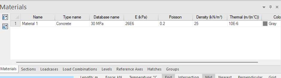
- Define Materials
- Import concrete grade (e.g., 30 MPa).
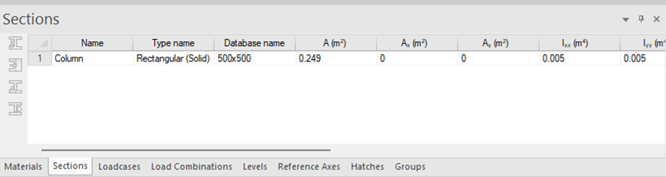
- Define Sections
- Add column section: 500 × 500 mm.
- Add Supports & Columns
- Go to Structure → Add Pad Footing.
- Edit stub length and footing dimensions.
- Copy footings to create a 25 × 25 m grid.

- Insert columns at grid intersections.
- Copy columns using Array Copy.

- Define Story Levels
- Set up Ground, First, till the last levels.

- Insert the Shear Wall
- From Surface Elements → Wall
- Define:
- Thickness (e.g., 400 mm).
- Mesh Size (e.g 0.25)
- Material (Concrete 30 MPa).
- Height: The wall can be continuous through multiple stories or defined per floor.
- Assign Supports & Boundary Conditions:
- Define support underneath the wall: Line Support, pinned or any type of support designer prefers.
- Ensure wall edges connect rigidly to floor slabs.

- Insert Slab
- Switch to first floor to define the perimeter of the slab
- From the Surface Elements panel, choose Slab.
- Define the perimeter of the slab along the corner columns in the model:
- Thickness: 300mm
- Mesh size: 0.25m
- Material (Concrete 30 MPa).
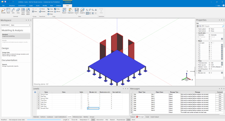
- Copy slabs and columns for remaining floors.

- Apply Loads
- Self-weight (automatic).
- Live loads (slabs).
- Lateral loads (wind/seismic).

- Run Analysis
- Linear Analysis → check sway reduction.
- Second-Order Analysis → for slender walls.
- Seismic analysis if applicable.
- Output & Design
- Contour plots: axial and shear stresses.
- Integration strips: forces in wall.
- Extract moments (Mx, My) and shears (Vx, Vy).
Shear wall reduces sway, attracts significant lateral forces.
Modelling a Steel Frame Without Bracing
- Create a Simple frame using steel members.
- Assign material: Structural Steel (e.g., S355).
- Define cross-sections for beams and columns.
- Apply supports at the base.
- Add same load cases as before.
- Live Loads
- Dead Loads
- Wind loads

- Run a Second Order Analysis.
- Observe sway displacements in the unbraced frame.
Add Bracing to the Steel Frame
- Insert diagonal braces.
- Assign steel material and section.
- Connect braces between columns and beams.
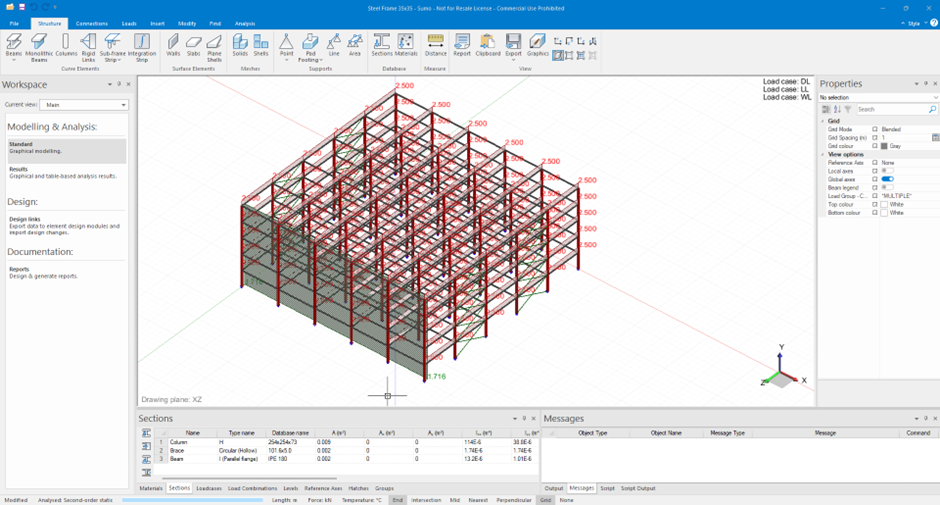
- Rerun the analysis.
- Compare sway reduction between unbraced vs. braced steel frame
Integrate Shear Wall into the Braced Model
- Combine steel frame + concrete shear wall in the same model.
- Define interface connection: rigidly connect wall edges to the frame.
- Run analysis again.
- Compare displacements, member forces, and sway effects.
- Highlight how the shear wall stiffens the structure.

Run Analysis
- Perform a Second-Order Analysis in solver settings.
- Compare:
- Sway magnitudes.
- Show how second order effects become critical in slender, unbraced frames.
Access Output
- View Displacements → compare sway values.
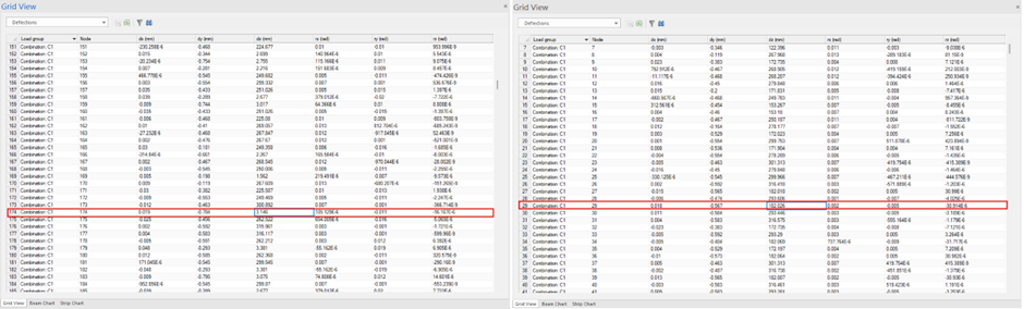
- View Forces & Moments → in braces, columns, and walls.
- Check Contour Plots on the shear wall.
Conclusion
- Unbraced steel frame → high sway, not stable.
- Braced steel frame → sway greatly reduced.
- Shear wall → provides significant lateral stiffness, reducing sway further.
- Second-order analysis → essential to capture true sway behaviour.
Was this helpful?
Thanks for your feedback!
