

Timber Trusses are strong, triangular framework of wooden beams used in construction to support roofs or floors, efficiently transferring loads to walls and allowing for large, open spaces without interior support.
Timber trusses are commonly used in:
- Residential roofing systems
- Industrial sheds
- Agricultural structures
Prokon SUMO provides 3D analysis and design capability. This chapter presents to demonstrate a step-by-step workflow for modelling, analyzing, and checking a timber truss using Prokon SUMO.
Defining Materials & Timber Sections
- Add Material: Timber Material (e.g., SA Pine Gr 8 or equivalent).

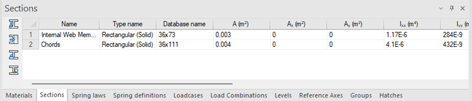
- Define Sections under the Sections Table → Rectangular timber section:
- Top and Bottom Chords: 38×111.
- Internal Web Members: 36×73.
Creating the Timber Truss Geometry
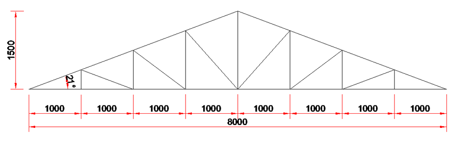
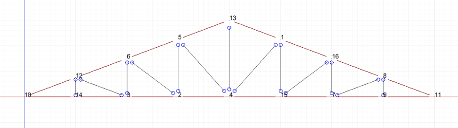
Before starting in SUMO, it’s important to understand the key components of a timber truss and the type of truss to model. In this example we will model a Howe Truss: Strong design with vertical members and diagonals facing opposite directions, used for wide spans and heavy loads. Members include:
- Tops Chords (Rafter) at 21°.
- Bottom Chords, 8m long.
- Internal Web Members (diagonals & verticals).
Member Releases and Support
Timber truss members are usually axial-force members.
Recommended release:
- Assign Pinned (P) releases at member ends for diagonals and verticals.
- This allows:
- Axial force transfer.
- No moment transfer at joints.
- Why?
- Reflects real truss behavior.
- Prevents unrealistic bending moments.
- This allows:
- Assign top and bottom chord releases at member ends as fixed.
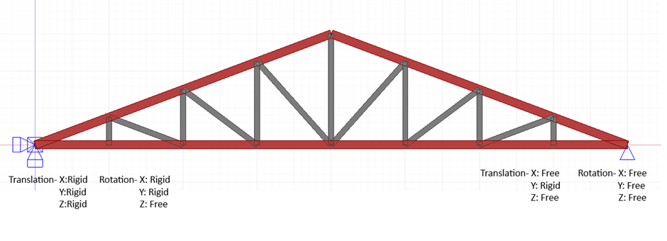
- To provide lateral support to the structure we add two supports on each end of the timber truss.
Assigning Loads
Load Types
Typical loads on timber trusses:
- Dead load – self-weight, roofing material
- Live load – maintenance
- Wind load – uplift and lateral effects
In SUMO:
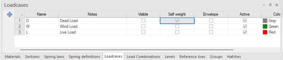
- Create load cases in Load Case Inputs table
Note:
Self-weight is automatically included if density is defined.
- Assign:
- Line loads to top chords
- Nodal loads if applicable

Defining Load Combinations
Load combinations are defined according to design codes.
Examples:
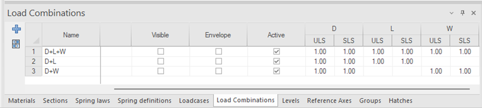
- Dead Load + Live load (D+L)
- Dead Load + Live load + Wind Load (D+L+W)
- Dead Load + Wind Load (D+W)
In SUMO:
- Navigate to Load Combination Input table
- Define Ultimate and Serviceability combinations
Running the Analysis
Before running analysis:
- Check Analysis Settings

- Check model connectivity.
- Confirm supports and releases.
- Validate load directions.
- Click Solve to Run the Analysis.
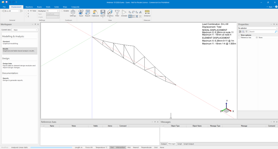
Review:
- Deformed shape
- Stability of the structure
Accessing Output
Key results to review:
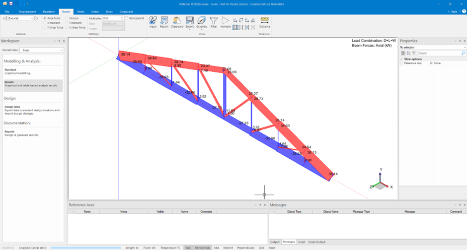
- Axial forces in members
- Deflections
- Reaction forces at supports
Useful views:
- Axial force diagrams
Deformed shape

Load case comparison
Purpose:
Confirm that the truss behaves as expected structurally.
Timber Member Design Check
SUMO integrates with Design Links for member checks.
Checks include:
- Axial tension and compression
- Slenderness
- Buckling
- Utilisation ratios
Steps:
- In the Workspace navigator, activate Design Links
- Go to Design tab > Timber panel > TimSec
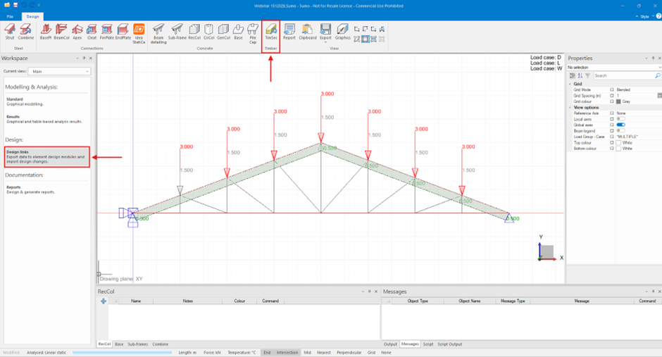
- When prompted, select all the elements in the model, and press Enter.
- In the Timber Member Design Dialogue, select all the load cases and combinations, and click OK to launch Timber Beam

- Proceed to Timber Truss Design.
Timber Truss Design
In Timber Beam, continue with the file exported from Prokon SUMO,
- Save the file as Timber Truss Design
- Select the design code to SANS 10163-2:2003, file> Code of Practice or navigate at the bottom screen and double click on the Code of practise and the dialog will populate.
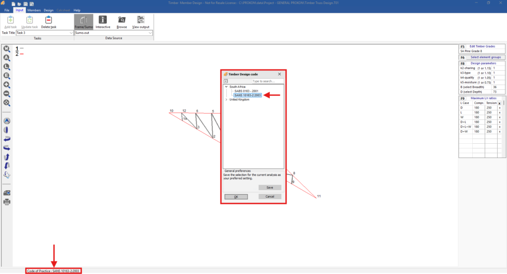
- Edit Timber Grade, Click on F5
- Select SA Pine Grade 8
- Select Element Group, click on F6
- Select the group that contains the rafters
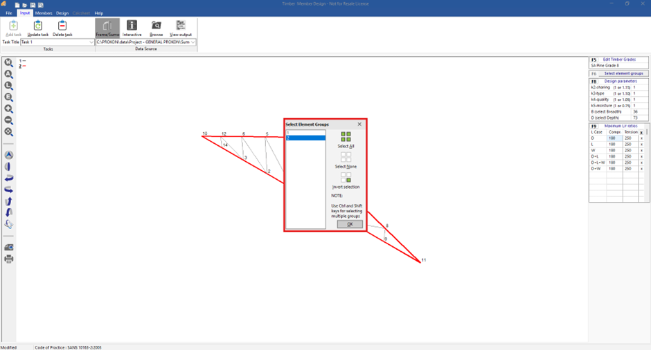
Enter the design parameters as shown:

- Confirm that Maximum L/r ratios for compression and tension are 180 and 250 respectively for all load cases and combinations.
- Go to the Task Panel and set the task title to task 1
- Click Add task
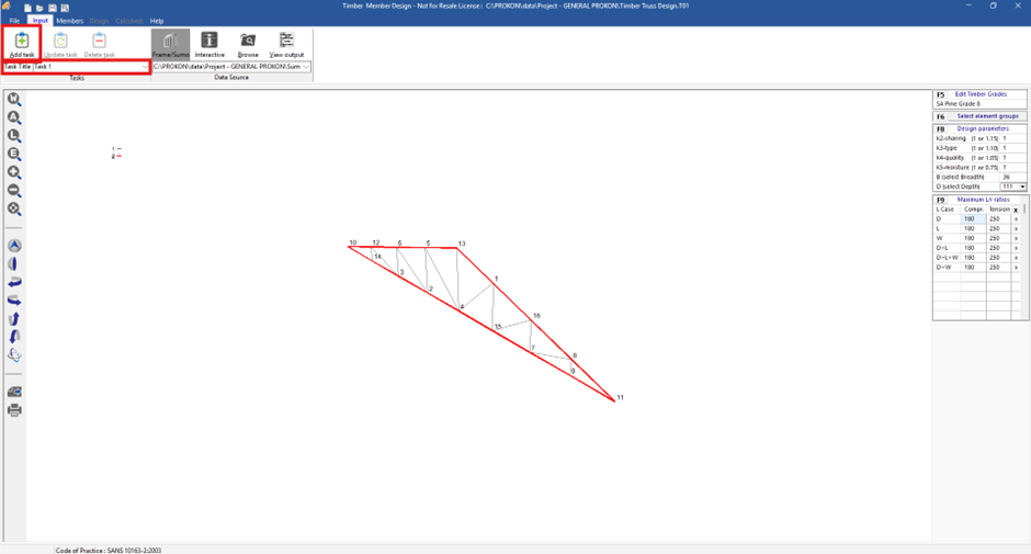
- Go to Members tab
- Select the all the values for Kx, Ky and Ke:
- Kx – Effective length factor for buckling about the x-axis (factors for members subjected to compression)
- Ky – Effective length factor for buckling about the y-axis (factors for members subjected to compression)
- Ke– Effective length factor for lateral torsional buckling about the x-axis (Factors for bending)
- Click in a Ke cell, In the effective length factor: Ke dialogue, fill value enter 1.92
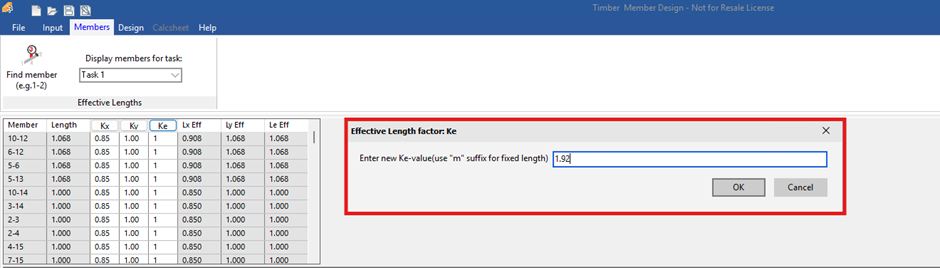
- Click OK to change all the Ke values
- Go to Design Tab > Element Panel
- Cycle through the results for each member
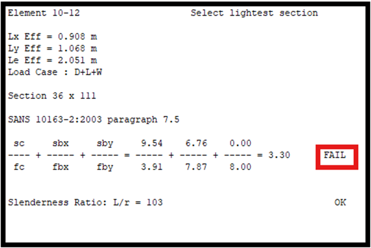
Some of the members fail the interaction equation check, we need to optimise the rafter design.
Task 2: Optimize Rafters
- Go to input tab> tasks panel and set the task title to task 2
- Click add task
- In design parameter F8, change B and D to Auto
- Go to Tasks panel > update task
- Go to Design tab> Element Panel
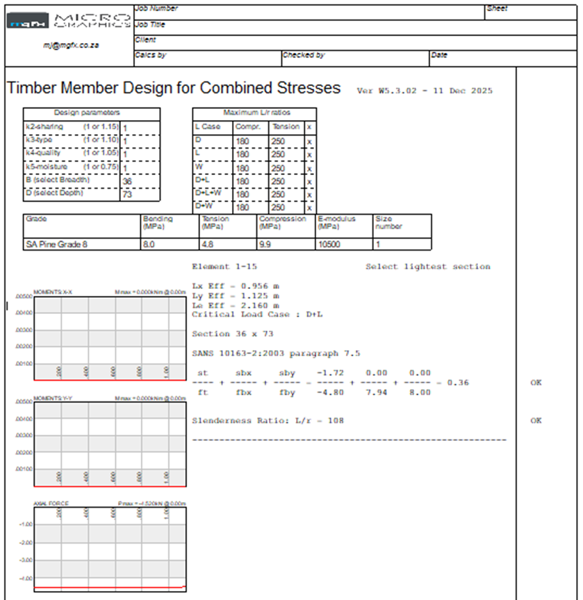
- Cycle through the results for each member. All members pass the interaction Equation check. Certain sizes have been resized.
Task 3 – Evaluate current Internal Members
- Go to the Input tab> Tasks panel and set the task title Task 3
- Click Add Task
- Select Element Groups, click on F6, select the group that contains the internal members.
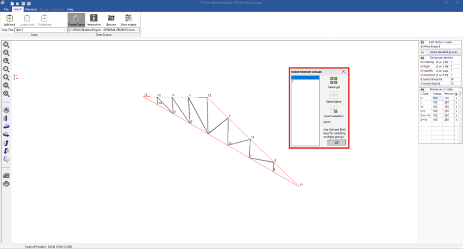
- In Design Parameter F8, change B and D to 36 and 73 respectively
- Click on update task
- Go to members’ tab
- Click the column header for Ke
- In the effective length factor: Ke dialogue, change the value to 1 and click OK
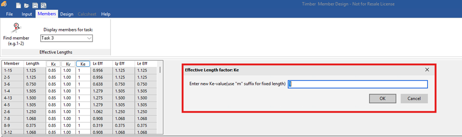
- Go to Design tab> Element Panel
- Cycle through the results for each member
- Go to Reporting panel> Task to Calcsheet
Task 4 – Optimise internal members
- Go to input tab> tasks panel and set the Task Title to Task 4
- Click Add task
- In Design Parameters F8, change B and D to Auto
- Go to Tasks panel> Update task
- Go to Design tab> Element Panel
- Cycle through the results for each member
All members pass the Interaction Equation check. Certain section sizes have been resized.
Reporting
- Go to Reporting panel> Task to Calcsheet
- Go to Calcsheet tab to view detailed results for all members and tasks that have been added to the calcsheet.
Conclusion
- Timber trusses should be modelled as pin-jointed systems
- Correct material and section definitions are critical
- Load combinations govern design
- SUMO provides a clear workflow from modelling to design checks
