

The Masonry Wall Design module in PROKON provides engineers with a powerful tool for verifying the structural resistance of unreinforced masonry walls under different loading conditions. The module is designed to simplify compliance with major masonry design codes while offering flexibility in modelling various wall configurations and support conditions.
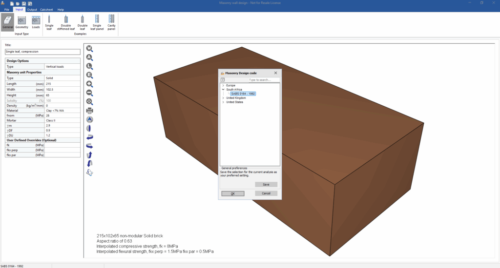
Code of practice support is currently limited to SABS 0164-1992. Characteristic compression strengths for masonry units are calculated based on unit geometry, nominal strengths and tables in the that code of practice.
Supported Loading Types
- Bearing walls
- Walls supporting slabs or beams
The module currently evaluates walls subjected to one of the following individual loading scenarios:

In-Plane Loading
Used for walls carrying vertical compressive loads, such as:
- Bearing walls
- Walls supporting slabs or beams
This loading checks the wall’s ability to resist axial compression with possible eccentricity.
Out-of-Plane Loading (Biaxial Bending)
Used when the wall behaves like a plate or panel, such as:
- Wind-loaded wall panels
- Free-standing or simply supported walls
- Walls subject to lateral earth pressure
This mode checks bending resistance about both principal axes.
Supported Masonry Unit Types
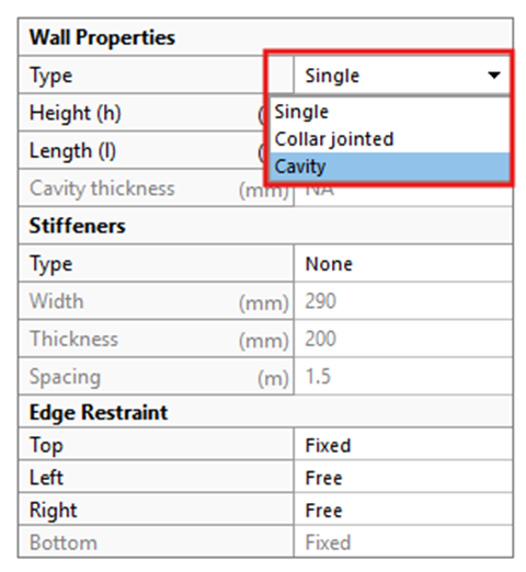
The module allows design using three common masonry unit categories:
- Single-leaf wall
- Collar-jointed wall
- Cavity wall
Each wall type is designed according to the selected code’s requirements.
Vertical Stiffness Options
Depending on the selected loading type, you can model additional vertical stiffening elements such as:
- Intersecting walls, or
- Nominal piers

These elements enhance stability and increase the wall’s resistance capacity.
Design Workflow Overview
Select Loading Type
Choose between:
- Vertical load (in-plane loading)
- Lateral load on panels (out-of-plane loading)
2. Define Geometry and Materials
Specify:
- Unit type and size
- Mortar properties
- Wall thickness and configuration
3. Apply Boundary Conditions
Support conditions and vertical stiffness elements are defined as applicable.
4. Review Design Results
At the bottom of the screen, a results table compares:
- Applied actions vs Calculated resistances
Each check displays a pass/fail result based on the chosen design code.

Calculation Sheet
The Calc Sheet provides:
- A clear summary of all inputs
- Step-by-step design calculations
- Code references for verification and audit requirements.

It is ideal for:
- Design reports
- QA/QC reviews
- Submissions to authorities or clients
