

Introduction
Prokon Padds is a specialist detailing tool designed for producing reinforced concrete drawings and bending schedules that are accurate, clear, and compliant with International and South African detailing standards.
The software bridges the gap between structural analysis and detailed reinforcement documentation, enabling designers to efficiently convert calculated reinforcement into fully coordinated drawings.
This chapter provides a foundational workflow for detailing reinforced concrete elements—including slabs, beams, columns, and pad footings—within PROKON Padds. It also guides users through project setup and bending schedule generation.
Setting Out a Project in Padds
Accurate and organised project setup is essential before detailing begins. Padds provides structured, configurable environments that promote consistency across all drawings and reinforcement schedules.
Creating a New Project
To begin a new project:
- Open Padds
- Select New Drawing, or navigate to File → New
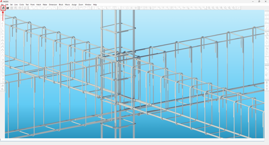
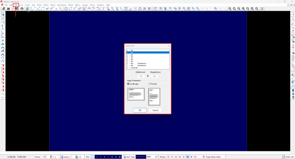
Define drawing-specific parameters such as:
- Sheet size (A0–A3 standard, or custom)
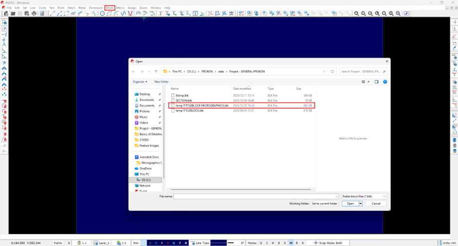
- Title block (Load an existing title block template as block)
A clean drawing environment ensures that reinforcement is placed accurately and consistently throughout the detailing process.

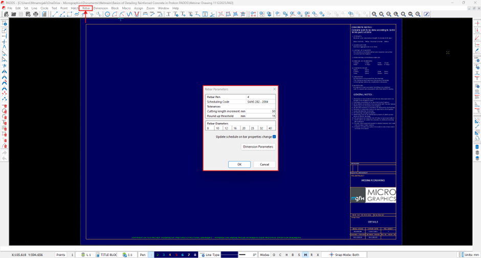
Setting Units and Standards
Before detailing, configure global settings to align with project requirements:
- Units: millimetres, metres
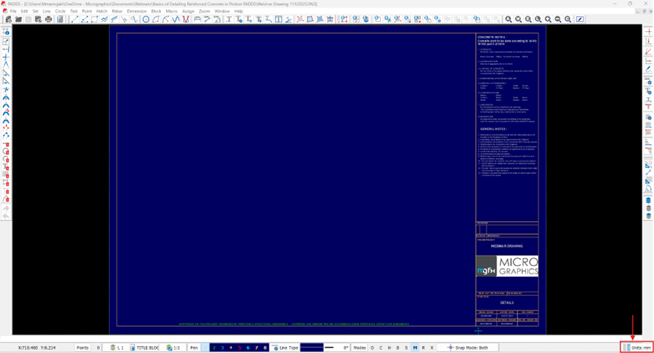
- Standards: SANS, BS, Eurocode, or project-specific standards
- Clear cover: as per applicable code or engineer’s specification
Selecting the correct standards ensures automatic bar shapes, bending parameters, and reinforcement rules comply with the governing code.
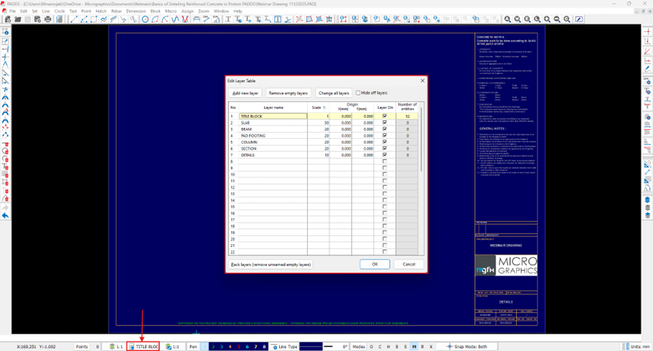
Layer and Style Management
Organise the drawing environment using a consistent layer system. Recommended layer types include:
- Concrete outlines
- Bottom reinforcement
- Top reinforcement
- Links / ties
- Text and annotations
- Dimensions
- Bending schedules
Clear layer naming conventions improve drawing clarity, avoid clashes, and support smoother coordination with engineers and contractors.
Detailing Reinforcement in Padds
Slab Reinforcement
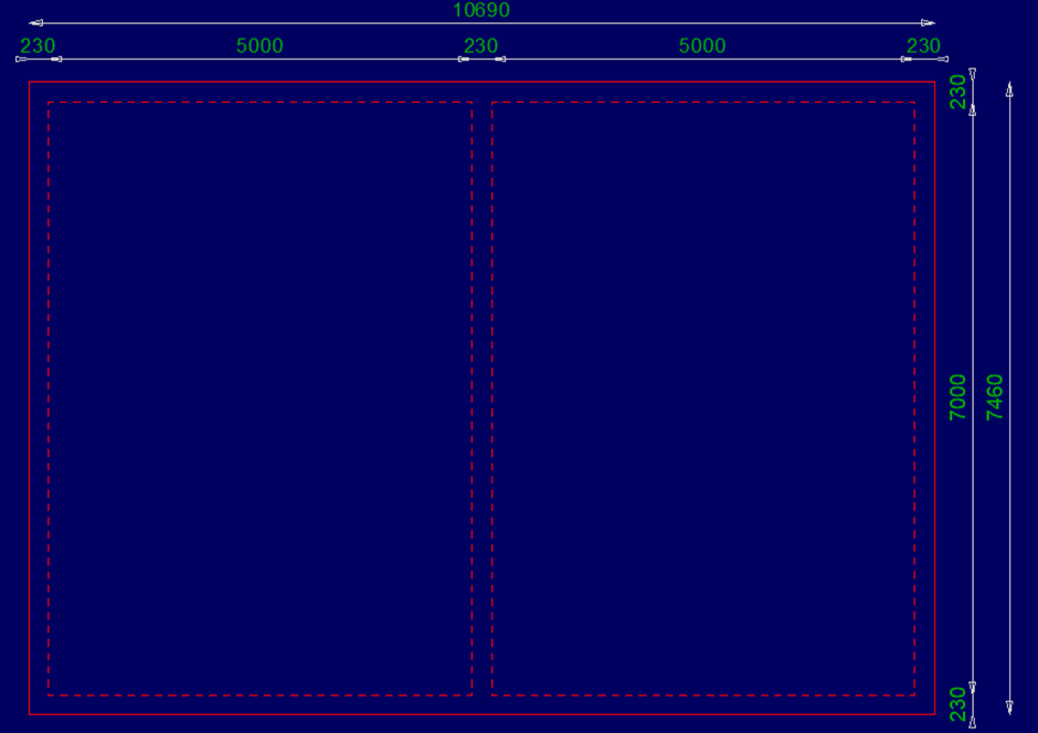
Drawing the Slab Layout
- Draw slab boundaries.
- Define spans, directions of reinforcement, openings, steps, or drop panels.
- Insert centrelines or grids for accurate referencing.
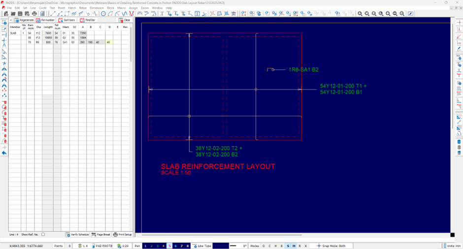
Adding Reinforcement
Use the following commands:
- RM – Reinforcement Multiple Bars
- RB – Reinforcement Single Bar
Typical slab detailing includes:
- Bottom reinforcement (main tension layer)
- Top reinforcement (over supports, openings, or cantilevers)
- Stools or chairs where required
- Lap lengths as per code
Beam Reinforcement
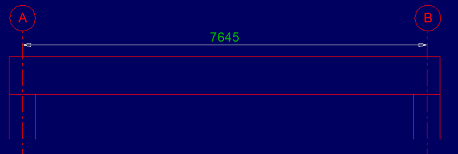
Beam Geometry
Draw the beam outline showing:
- Depth and width
- Clear cover
- Support locations
- Column or wall connections
Flexural Reinforcement
Detail:
- Bottom tension reinforcement
- Top reinforcement at supports
- Extra bars in hogging regions
- Side face reinforcement (if required for deep beams)
Ensure spacing satisfies:
- Maximum spacing limits
- Shear resistance requirements
- Confined regions near supports

Column Reinforcement
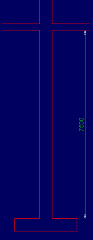
Column Geometry
Set the column’s cross-sectional dimensions, ensuring consistency with structural models.
Longitudinal Bars
Define:
- Number of bars
- Diameter
- Layout (square, rectangular, circular)
Ensure:
- Minimum 4 bars for rectangular
- Minimum 6 bars for circular
Transverse Reinforcement
Detail:
- Ties or spirals
- Hooks and laps
- Confined regions at ends
- Joint reinforcement where beams intersect the column
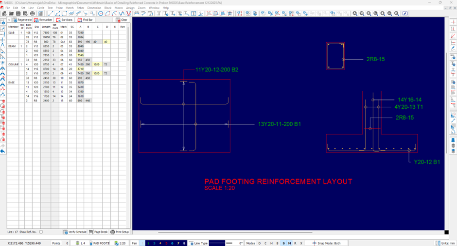
Pad Footing Reinforcement
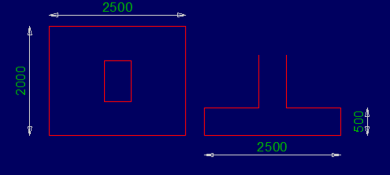
Geometry
Draw plan and section showing:
- Footing length, width, and depth
- Column/pedestal footprint
- Sloping faces or projections if applicable
Reinforcement Layout
Include:
- Bottom reinforcement mesh or bar mat
- Additional bars around the column footprint
- Top bars for temperature and shrinkage
- Hooked bars in accordance with code
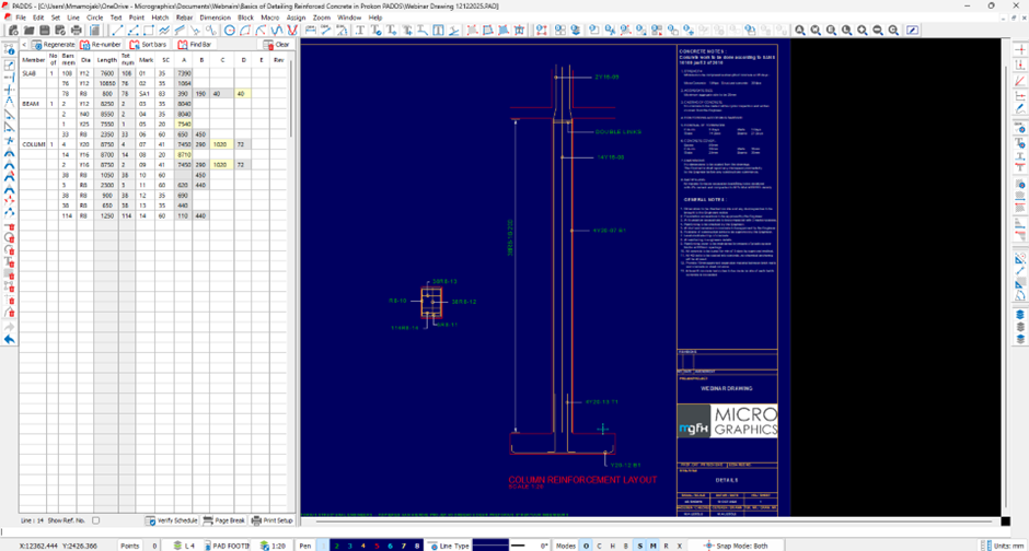
Accessing the Bending Schedule
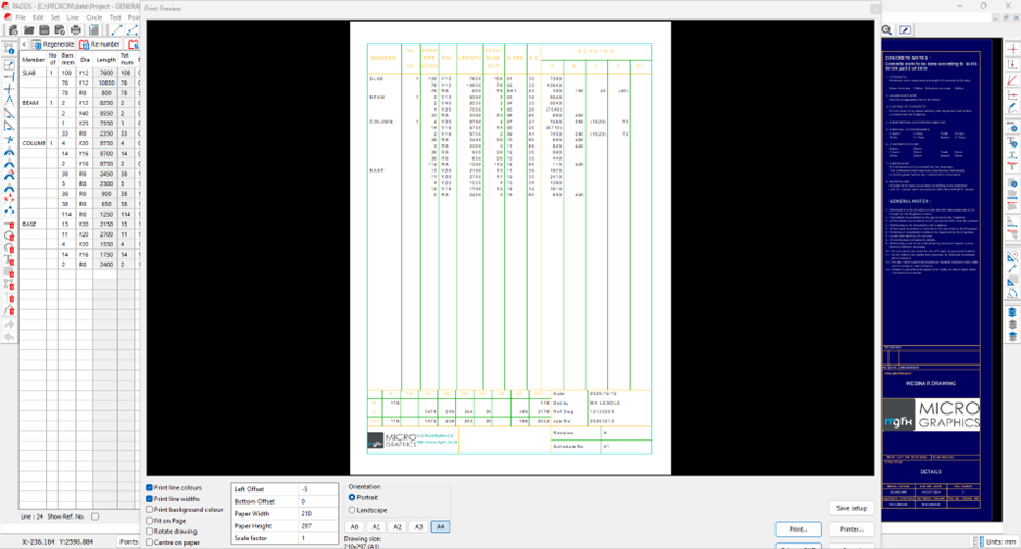
One of Padds’ most valuable features is the automatic generation of a bending schedule directly from the drawing.
Generating the Schedule
- Navigate to Bending Schedule panel.
- Padds automatically extracts:
- Bar mark numbers
- Bar shapes and shape codes
- Lengths and bending dimensions
- Quantities and total lengths
- Bar weights
This ensures full coordination between reinforcement drawings and schedules.
Editing and Updating the Schedule
- Edit bar marks directly from the schedule
- Modify bars graphically in the drawing
- Regenerate the schedule after design changes.
- Export schedule to DXF or PDF if required.
Ensuring Compliance
Schedules follow the relevant reinforced concrete code (e.g., SANS 282, BS 8666), ensuring contractors receive correct instructions.
Conclusion
Prokon Padds offers an efficient and structured environment for detailing reinforced concrete elements. By following a consistent setup and detailing workflow, engineers and technicians can produce drawings that:
- Are code-compliant
- Communicate reinforcement requirements clearly
- Reduce site errors
- Integrate seamlessly with structural design modules
Users are encouraged to experiment with different detailing tools within Padds and apply best practices to improve accuracy and workflow efficiency.
